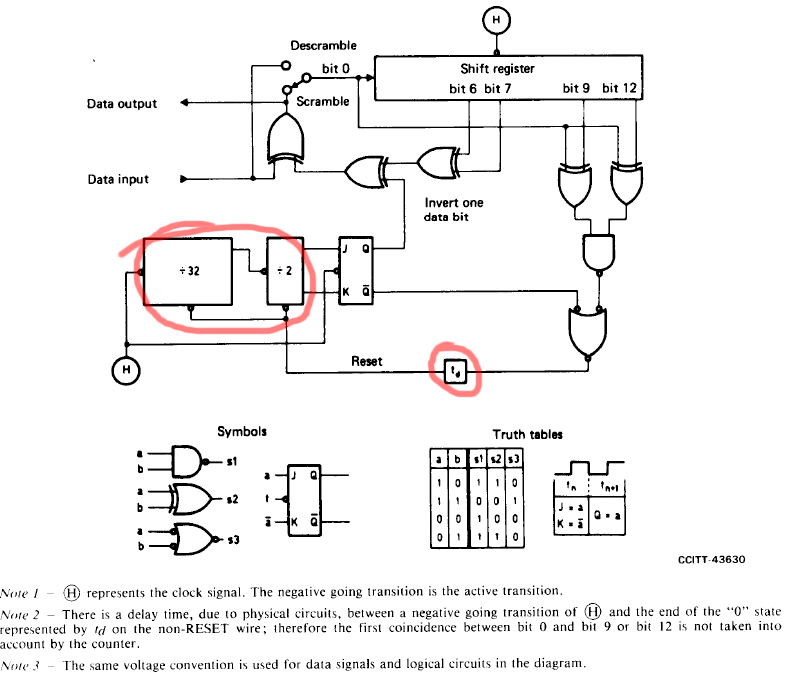
I want to simulate the scrambler/descrambler device provided in ITU-T Recommendation V.27, but the circuit diagram has some weird logic gates I can't make sense of. I'm talking about those "÷32", "÷2" and "\$t_d\$" gates (circled red).
 As far as I understand, "÷32" and "÷2" gates are supposed to be clock signal dividers, but if so, what do the bottom pins do and what's "\$t_d\$" for? Is it a time delay? It reads so, but the whole purpose of them looks too cryptic to me and I am not sure what gates should I use, say, in Protues to correctly emulate this thing.
2 Answers
What you call an ":" is a divide symbol, NOT a ":".
Below Divide = "/". :
So /32 = divide by 32 = 5 stage counter.
Each stage divides by 2 in a binary counter (eg CD4040) so for 1 2 3 4 5 stages the divide ratio is 2 4 8 16 32.
/2 is a one stage counter = a flipflop configured to toggle when clocked.
The bottom lines do what the labels says = reset line.
The dividers are reset to 00000 and 0 respectively.
The box labelled "td" is explained in note 2 - it's a time delay - read the note.It's not complicated - it means EXACTLY what it says. ie there is a delay due to physical circuit parameters.
-
\$\begingroup\$ Is it that hard to use the ÷ symbol? Google for 'unicode divide' and cut and paste, or use the math mode and
\\$\div32\\$\$ \div32 \$ \$\endgroup\$ Commented May 14, 2016 at 14:38 -
\$\begingroup\$ I've read the note but overthought it beacuse of the notation :) \$\endgroup\$– DimitryCommented May 14, 2016 at 14:43
-
\$\begingroup\$ @PeteKirkham Rather than beating about the bush I'll just say straight out that I find your passive aggressive ed in as boorish. That doesn't mean that that was intended or that is how it is, it's just how I find it. || Is it that hard to be polite in your comments - eg you could say something like. "FYI - the unicode symbol for division is ÷ ÷ ö ÷ \$\endgroup\$– Russell McMahon ♦Commented May 17, 2016 at 7:27
-
\$\begingroup\$ @PeteKirkham Rather than beating about the bush I'll just say straight out that I find your passive aggressive lead in both unnecessary and boorish. That doesn't mean that that was intended or that is how it is, it's just how I find it. || Is it that hard to be polite in your comments? - eg you could say something like. "FYI - the unicode symbol for division is ÷ . | Not that that would be itself do any good as not only your assumption that everyone knows that unicode can be used in this context incorrect, but you in fact cannot do so directly in all unicode forms, and knowing which ... \$\endgroup\$– Russell McMahon ♦Commented May 17, 2016 at 7:33
-
\$\begingroup\$ forms do work takes additional knowledge. eg using &H247 does not work here. You may know why and it may be obvious to yu what to do but, why not instead of the usually rude "Ask Google" suggestion, actually provide the requisite information. | I suggest that it's easier if using Windows (and mayhaps otherwise also) to use ALT+246 (numerics on RH keypad) or ALT+ 0247 yielding ÷ and ÷ respectively. No? . \$\endgroup\$– Russell McMahon ♦Commented May 17, 2016 at 7:37
The 2 divider blocks are divide by 32 and divide by 2. That is simply implemented by a 5 bit binary counter (div32) and a D flip flop with \$\overline Q\$ tied to the D input.
The purpose of the time delay is explained in note 2 and is to ensure reset is not asserted too early.
The delay should be greater than the gate delays of the path from H at the shift register to the delay block. This is the sum of the delays from the clock asserting at the shift register to its outputs updating, plus the longer of the delays from bits 9 and 12 through the gates to the delay block.
Most simulators have a simple delay function ( I am not a Proteus user, so I cannot say what it can use).
Note that the circuit diagram is using assertion level logic
-
\$\begingroup\$ Agh - dual answers in preparation I see. Our answers about match :-) \$\endgroup\$– Russell McMahon ♦Commented May 14, 2016 at 13:38
-
\$\begingroup\$ Well, I am glad they did match. \$\endgroup\$ Commented May 14, 2016 at 13:39
-
\$\begingroup\$ Your delay answer was much better than mine. I commented on the reset line and the CD4040 mention may at least give him a clue. So non lock-step matching is good :-). I mentioned the toggling FF but you added Qbar-D connection. (Why won't my JK toggle when I do what you say :-) :-) :-). ) \$\endgroup\$– Russell McMahon ♦Commented May 14, 2016 at 13:50
-
\$\begingroup\$ I added a note that the circuit is using assertion level logic, which can be confusing to the uninitiated. \$\endgroup\$ Commented May 14, 2016 at 14:43
