2
\$\begingroup\$

I'm sure this is a pretty basic question, but I wanted to run it by you guys before creating my PCB.

I want to have two LEDs on the board to indicate the global state of the board. When the board has power, but the MCU is not in an active mode I want the Red LED to light up, and when the MCU puts a pin high I want the red led to be replaced by a green led instead.

I want to solve the problem using simple electronics, and not with RGB led, etc.

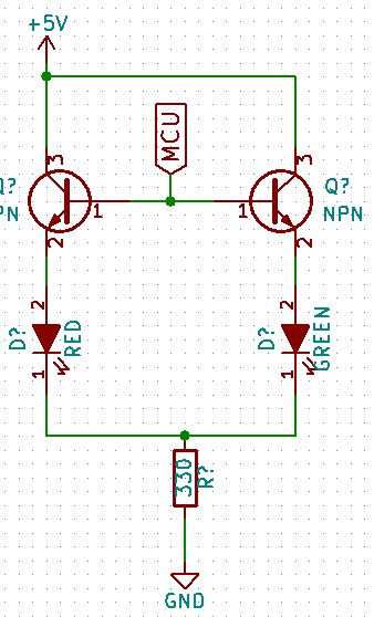
My idea is to use two transistors. One which is normally closed (the green one), and one which is normally open (the red one), and then toggle them on/off using a signal from the MCU.

Does the following circuit make sense?

enter image description here

Edit: Lots of good suggestions here. The MCU is a Teensy 3.2, which has 3.3V output, and 25mA Max current on the digital GPIO pins. I have both 3.3V and 5V powersources available on the board.

\$\endgroup\$
3
  • 1
    \$\begingroup\$ With that circuit, the signal from the MCU will control the two LEDs together - either both will be on, or both will be off. \$\endgroup\$ Commented May 15, 2016 at 21:08
  • \$\begingroup\$ I was thinking there is two different kinds transistors (and this is where I'm not strong enough in my transistor knowledge...) One which "closes up" when the pin is driven high, and the other which "opens up" when the pin is driven high. So I just want one of them to be active at any given time. \$\endgroup\$ Commented May 15, 2016 at 21:11
  • \$\begingroup\$ See the answer for this Q: electronics.stackexchange.com/questions/234252/… When driving from an MCU, you can remove D4, D6 and R2 from that circuit. \$\endgroup\$
    – jp314
    Commented May 16, 2016 at 1:19

8 Answers 8

1
\$\begingroup\$

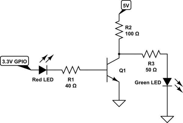
You can use a transistor as a switch here.

schematic

simulate this circuit – Schematic created using CircuitLab

So when the GPIO is low or zero then the transistor would be in cutoff region and the green LED glows and when the GPIO is 3.3 V the red LED glows since the transistor goes in saturation state the Green LED would be switched off.

The resistors values are so chosen that the transistor work as a switch.


EDIT : Writing KVL's will let you know the values of resistors.

Let 0.7v be across the base emitter junction when 3.3V is given at GPIO pin, 1.8V across red LED, Let the voltage at collector emitter junction be 0V when saturated so at this voltage the green LED will not glow.

Also let Ib be the current and is generally 20mA for a normal 5mm LED

  1. KVL at B-E of transistor : $$3.3V-0.7-1.8V-I_bR_1=0 $$ We require about 20mA in the red LED so R1=40 ohm

  2. When the transistor is in cut-off state i.e., no voltage at GPIO pin & the voltage at collector is around 5V so KVL at C-E junction of transistor : $$5V-2V-I_3R_3-I_CR_2=0$$

2V= forward voltage of green LED and let 20mA of current is required for the green LED so R2+R3=150ohm, I3=Ic=20mA assuming no current flows through the transistor since Vc=0V.

So choose R2=100ohms and R3=50ohms

Note : we choose R2 to be 100 because we do not want large current to be flowing through the circuits at collector when transistor is cutoff.

\$\endgroup\$
4
  • \$\begingroup\$ I like it! Only three resistor, and one transistor sounds appealing. Can you elaborate as to what resistor values to use? \$\endgroup\$ Commented May 16, 2016 at 9:35
  • \$\begingroup\$ @FrodeLillerud I have edited the answer! \$\endgroup\$
    – Jasser
    Commented May 16, 2016 at 10:51
  • 1
    \$\begingroup\$ Thanks, I like the simplicity, and choose this as the answer. \$\endgroup\$ Commented May 16, 2016 at 19:09
  • \$\begingroup\$ How to turn this circuit into gpio input? GPIO output could be HIGH and LOW; 2 GPIO inputs A and B; A should be high if output high; B should be high if output low; \$\endgroup\$
    – br.
    Commented Dec 8, 2018 at 8:50
5
\$\begingroup\$

Something like this should work:

schematic

simulate this circuit – Schematic created using CircuitLab

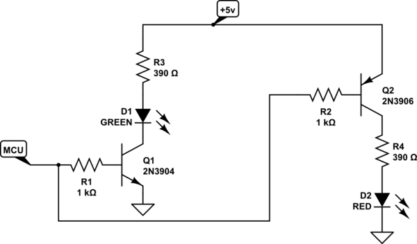
If the signal from the MCU is Low, the red LED will be on, if High, the green LED will be on.

An NPN transistor (such as 2N3904) will conduct when the base is more positive than the emitter. A PNP transistor (2N3906) will conduct when the base is more negative than the emitter. Resistors are required in the base lead to limit the base current.

\$\endgroup\$
4
  • \$\begingroup\$ Thanks! Could the two transisors share one 1k resistor? And could the leds also share the 390ohm resistor? In theory only one of the partial circuits is going to be active at any given moment, so current shouldn't be a problem for the resistors, right? \$\endgroup\$ Commented May 15, 2016 at 21:42
  • \$\begingroup\$ You need separate base resistors, as the NPN base cannot go more than about 0.7 volt positive of its emitter, and the PNP base cannot go more than about 0.7 volt negative of its emitter. I don't think you can re-arrange this circuit to allow the LEDs to share a resistor. \$\endgroup\$ Commented May 15, 2016 at 22:14
  • 1
    \$\begingroup\$ This won't turn off the PNP if the mcu is under 5V. \$\endgroup\$
    – Passerby
    Commented May 16, 2016 at 0:42
  • \$\begingroup\$ @PeterBennett, D2 is always on. I changed R2 to 10K and put Q2 down (Led and resistor between 5V and Q2.E and the collector to ground). I "breadboarded" this with Q1=2SC4604 and Q2=2SA1761, simulating MCU with a 1k pullup resistor and a switch to ground and it works. \$\endgroup\$
    – Antonio
    Commented May 17, 2016 at 15:46
3
\$\begingroup\$

enter image description here

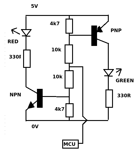
When the MCU goes HIGH (5V) the NPN transistor is turned ON, the PNP is turned OFF and the red LED comes ON.

When the MCU goes LOW (0V) the PNP transistor is turned ON, the NPN is turned OFF and the green LED comes ON.

With NO input from the MCU (mid point floats to 2.5V) both transistors (and LEDs) turn ON.

EDIT ADDITIONAL: For a 3V3 MCU reduce the top 4k7 resistor (E-B of the PNP) to 2k2.

\$\endgroup\$
2
\$\begingroup\$

schematic

simulate this circuit – Schematic created using CircuitLab

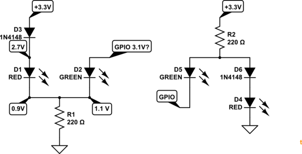
Figure 1. Transistorless option. The 0.9 V reading is obtained with GPIO turned off. 1.1 V reading is with GPIO turned on. Figure 2. Negative rail switching version.

I haven't tested this but the theory is ...

  • With GPIO off D1, RED, lights. The voltage drop across D3 and D1 will be about 0.6 + 1.8 = 2.4 V.
  • When GPIO pulls high D2, GREEN, lights. The voltage drop across the green led will be about 2.0 V. Since this is less than required by D1 / D3 the current will fall in the RED led and it will go quite dim. I've assumed some voltage droop when the GPIO is supplying current.

This circuit can be inverted if GPIO pull low is preferred. No transistors.

\$\endgroup\$
3
  • \$\begingroup\$ "No transistors"... And your name is transistor XD. One thing I could criticise the circuit is the green LED has more current going through than the red one. Additionally green LEDs are brighter than red ones. But I applaud for your simplicity. \$\endgroup\$
    – Bradman175
    Commented May 16, 2016 at 0:22
  • \$\begingroup\$ I've added some moremore info about voltages in the question. Will this solution still work? \$\endgroup\$ Commented May 16, 2016 at 5:23
  • \$\begingroup\$ It should. Answer updated. \$\endgroup\$
    – Transistor
    Commented May 16, 2016 at 10:38
2
\$\begingroup\$

Wow the anwsers to this are complicated. But your circuit is already pretty close. What you're describing is actually a simple differential / ltp circuit. Just disconnect one of the bases and connect it to a voltage divider making 2.5V. When the transistor connected to the MCU is low, it will not provide an current and all current will be diverted to the other transistor. When the MCU is high, that transistor will consume all current and the other transistor will turn off (because the common emitter resistor of the differential / ltp will present a voltage higher than Vbe of the second transistor).

However, you may also need to move the LEDs to the collectors because the voltage drop may cause issues with the differential action.

\$\endgroup\$
1
\$\begingroup\$

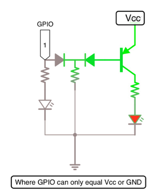
This is an inverter circuit. I have used this circuit to answer other questions and it works perfectly. The Resistor in the middle should be about 1KΩ.

enter image description here

\$\endgroup\$
3
  • \$\begingroup\$ I've added some more info about voltages in the question. Will this solution still work? Also, do you have component names for the diodes and transistor? I'm using SMD. \$\endgroup\$ Commented May 16, 2016 at 5:25
  • \$\begingroup\$ If the GPIO pin is the same voltage level as the power supply (in which it is the 5v rail shown in the image) then it will work. \$\endgroup\$
    – Bradman175
    Commented May 16, 2016 at 5:43
  • \$\begingroup\$ I edited the image for better understanding \$\endgroup\$
    – Bradman175
    Commented May 16, 2016 at 5:50
1
\$\begingroup\$

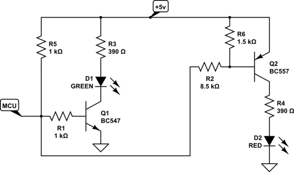
I tried Peter Bennett's circuit, and like Antonio, I too had the red LED on at all times. At first, I tried Antonio's modification to the circuit, but then I realized that it was wrong (even though it worked). Below is my modification of the circuit. I substituted a BC547 NPN and a BC557 PNP because it's what I had. I changed R2 to 8.5k, and added the 2 pull-up resistors(R5 and R6). When the MCU pulls the bases of both transistors to ground, the green LED turns off and the red LED turns on. I know this was an old post, but I figured I'd add to it since it somewhat helped me.

schematic

simulate this circuit – Schematic created using CircuitLab

\$\endgroup\$
2
  • \$\begingroup\$ Welcome to EE.SE. Note that when you use the CircuitLab button on the editor toolbar you can save your circuits inline and editable (and copyable). No need for screengrabs and no CircuitLab account is needed. \$\endgroup\$
    – Transistor
    Commented Jul 23, 2018 at 19:43
  • \$\begingroup\$ @Transistor Thank you. I was trying to figure out how to do that and had thought I needed an account. \$\endgroup\$
    – Swappart
    Commented Jul 24, 2018 at 22:07
0
\$\begingroup\$

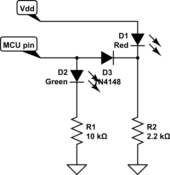
The following circuit should work nicely provided that the MCU pin has sufficient current drive. Both Microchip PIC and Atmel AVR chips have pins with sufficient current drive.

schematic

simulate this circuit – Schematic created using CircuitLab

I am assuming that you are using Superbright LEDs.

A typical Green Superbright LED drops about 3 Vdc and is blinding when run from 5Vdc with a 10k resistor.

A typical Red Superbright LED drops about 1.7 Vdc and is reasonably bright when run for 5 Vdc with a 2k2 resistor.

Operation is extremely simple: if the MCU pin is either high-impedance (set as Input) or is Low, the Red LED is lit and the Green LED is NOT lit.

When the MCU pin goes Hi, the Green LED is lit and the Hi level raises the cathode of the Red LED high enough that it is NOT lit.

This circuit works well with the PIC 16f microcontrollers that I use.

\$\endgroup\$
2
  • \$\begingroup\$ Bit similar to transistor's. Jeez this question has so many solutions that I could flag it as too broad. \$\endgroup\$
    – Bradman175
    Commented May 16, 2016 at 5:52
  • \$\begingroup\$ @Bradman175, but it is interesting to see how many way to do same thing. :-) \$\endgroup\$
    – Antonio
    Commented May 17, 2016 at 13:01

Your Answer

By clicking “Post Your Answer”, you agree to our terms of service and acknowledge you have read our privacy policy.

Not the answer you're looking for? Browse other questions tagged or ask your own question.