4
\$\begingroup\$

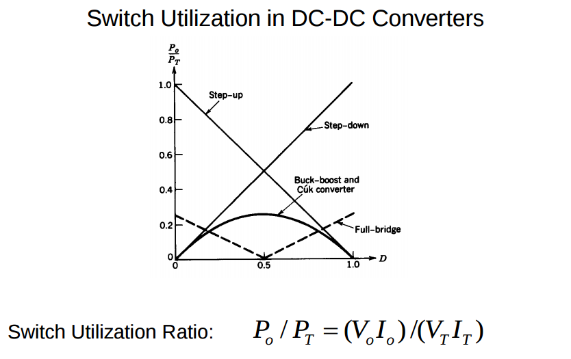
In the book, Power Electronics, by Need Mohan at the end of chapter 7, it is this image:

enter image description here

Relating the output power and the power that the transistor is handling, I want to reproduce this plot for the buck, boost and the buck-boost converters, but I don't quite understand how to write down the equations.

I understand the boundary values at D = 0, D = 1 for the buck and the boost since the transistor is either on or off during the whole period, But I'm not sure why the relations is completely linear.

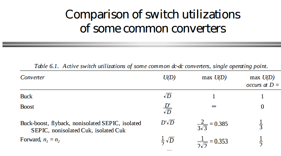
In the book, fundamentals of power electronics by Robert Erickson there is table regarding this subject

enter image description here

In this case, there are no plots, and obviously, the plots of this equations will be different that the ones in the above image.

Both, the images and the table give some kind of intuition that if possible it's better to use the buck or the boost converter instead the buck-boost.

I believe that both, buck and boost converters are more efficient than the buck-boost but is still hard for me to made that claim without more information. There is other book or article which covers this subject more in-depth?

\$\endgroup\$
2
  • \$\begingroup\$ What is "D"? Duty cycle of the switching transistor? \$\endgroup\$
    – tokamak
    Commented May 26, 2016 at 0:59
  • \$\begingroup\$ @tokamak yes, D is Duty cicle. \$\endgroup\$ Commented May 26, 2016 at 1:05

1 Answer 1

2
\$\begingroup\$

Erickson refers to this as indirect power. See page 5 of ECEN5807 Lecture 3.

Given on that slide: $$P_{indirect}=(DV_g)(D'I_L)$$

$$I_L*D'=I_g$$ $$P_{indirect}=D*V_g*I_g$$ $$P_{direct}=P_{in}=P_{out}=V_g*I_g$$ $$P_{direct}/P_{indirect}=1/D$$

This is close to what Mohan found, but I'm getting the inverse. Doing a similar process for a boost I get the same inverted result (1/D').

I hope this helps.

EDIT: It makes more sense for the switch utilization to be \$P_T/P_O\$ because the power "through" the transistor must always be less then the output power (keeping the ratio below 1.0). I think this is a typo in the book.

If this is true the equations for Buck:

$$P_T/P_O = D $$

For Boost: $$P_T/P_O = D'= (1-D)$$

For Buck Boost:

$$ P_T/P_O = D*D'$$

The values are different in Table 6.1 of Erickson because (I believe) he's using the RMS values of the switched Voltage/Current so these values can be related to switch loss.

This means, for example, that conduction losses of the transistor in a buck converter are related to \$\sqrt{D}\$.

\$\endgroup\$

Your Answer

By clicking “Post Your Answer”, you agree to our terms of service and acknowledge you have read our privacy policy.

Not the answer you're looking for? Browse other questions tagged or ask your own question.