3
\$\begingroup\$

I'm currently building a power supply using a MC34063 IC. I have used an external n-channel MOSFET for switching the high current used to drive an LED pair.
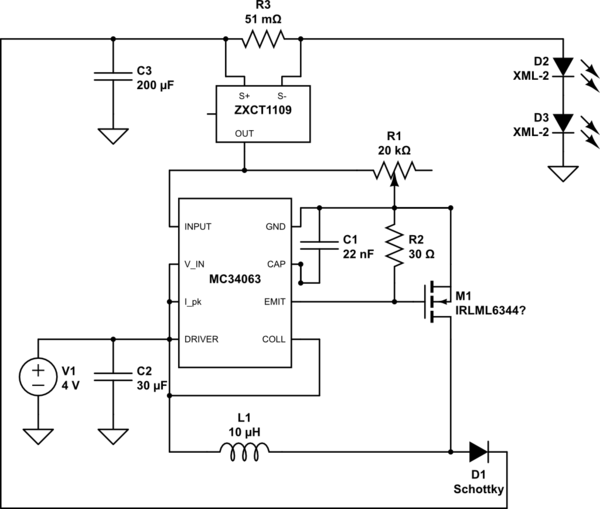
schematic

simulate this circuit – Schematic created using CircuitLab

The switch operates on a fixed duty cycle of about 6:1, frequency 40kHz. I have modified the circuit to run current mode, using a ZXCT1109 current sense amplifier and sense resistor. Gain is controlled by R1: whenever voltage at the INPUT node exceeds 1.25V, the internal comparator outputs low and the emitter output (i.e. gate voltage) stays low until the sense voltage drops below this threshold. Current is maintained via C3 decoupling capacitors.

At low currents (i.e. when current gain is high), the circuit operates fine: the switch correctly shuts down whenever current is above threshold. Decreasing gain while the circuit is operating leads to an increasing in gain, and the output stays stable. However, whenever I turn on the circuit again at this higher current, current feedback no longer works correctly, and the switch always turns on during its on cycle. Naturally this leads to an overcurrent condition and if I left the circuit on for more than a few seconds the MOSFET would fry. The LEDs continue to light up in the overcurrent, but at reduced intensity. Oscilloscope readings show the comparator input node voltage just reaching 1.25V at its peak before rapidly falling off. Non-fault readings have this voltage exceeding ~2V before slowly falling off as expected.

I strongly suspect this is due to current latchup as described here. The input steady state current threshold above which this occurs is around 1A. My benchtop power supply has a maximum current limit of 2A. This overcurrent problem does not occur whenever I use Li-ion batteries to power it.

I can understand why this is occurring on a very rough basis: the current limiting is preventing effective IC startup. However, I don't understand the effect any further than this. Why does the voltage at the comparator input node never go above threshold even though the current is definitely high enough to trigger it? Why would the current limit affect the circuit this much and prevent the trigger threshold voltage ever being reached?

The article suggests using a soft start measure to fix this. I know this works (since I did it manually via changing current after the circuit was already online), but the MC34063 lacks an internal soft start function. Is there any way to implement this in a relatively simple fashion?

I have not included oscilloscope readings but I can provide them if requested.

\$\endgroup\$
4
  • \$\begingroup\$ During start-up, the duty cycles will be higher and this can cause all manner of problems; one way to control the start-up into a heavy load is to step the operating frequency (low frequency permits a longer turn-on time for an effectively longer duty cycle). A capacitor across the timing capacitor that is switched in and out as necessary might do the trick. \$\endgroup\$ Commented May 30, 2016 at 15:07
  • \$\begingroup\$ That's interesting, but according to page 4 of the application note the duty cycle is fixed even during start up? Unless you mean the duty cycle of the output switch rather than the capacitor. In any case, would you possibly be able to elaborate why the latching occurs due to this? \$\endgroup\$ Commented May 30, 2016 at 16:47
  • 1
    \$\begingroup\$ What is your benchtop supply? Cheap Chinese supplies do not have clean power. \$\endgroup\$
    – Voltage Spike
    Commented Jun 1, 2016 at 17:34
  • \$\begingroup\$ It's a Farnell Instruments L30-2. Highly doubt it's cheap, or Chinese. \$\endgroup\$ Commented Jun 1, 2016 at 22:41

5 Answers 5

1
+50
\$\begingroup\$

I can not really figure out why the regulator does not limit the excessive current if you start with high current values. Maybe the current does not actually flow through the current sensor?

But I have a suggestion for a simple soft start.

schematic

simulate this circuit – Schematic created using CircuitLab

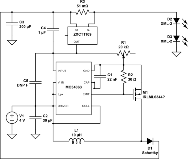
Consider the capacitor C5 between VCC and Input. On power up this will pull the input pin to VCC wich is higher then 1.25V. So the comperator inside MC34063 will not turn on the switch.

C5 will now be charged by R1 with a time constant of

$$\tau = R1 \cdot C5$$

For a current of 1A, R1 should aproxamately be

$$R1 = \frac{1.25V}{1A * 51 m\Omega \frac{124 µA}{30 mV}} = 5929\Omega \approx 6k\Omega$$

$$\tau = R1 \cdot C5 = 6k\Omega \cdot 1µF = 0.006 s$$

And after \$5\tau = 0.03 s\$ the capacitor will be almost fully (99.3%) charged. During this time the feedback of the current sensor will slowly take over. Once the Input voltage goes under 1.25V the PWM will start.

The only thing that is not quite nice with this solution that it might violate the maximum conditions of the ZXCT1109. It states that the Voltage between OUT and GND may not exceed \$-0.3\$ to \$V_{S+}\$. Since the diode D1 shout take care that the Voltage at S+ is almost the same as VCC this might still work.

To not violate the specifications do not use the capacitor as explained in position C5 but rather connect it as C4 between OUT and S+. This will work almost the same.

\$\endgroup\$
3
  • \$\begingroup\$ This looks interesting, but could this not end up capacitatively coupling the feedback voltage to the power trace, or vice versa? \$\endgroup\$ Commented Jun 1, 2016 at 22:44
  • 1
    \$\begingroup\$ Yes that is a possibility, you could put a resistor in series with the capacitor. That will limit those effects. You could also try to connect a P-MOS form VCC (source) to INPUT (sink) and a capacitor with a resistor in series from gate to GND. That should tie the input high as well but when when the capacity on the gate is charged the connection is broken. The resistor and the capacitor at the gate will determine the time it takes for switching just as above. \$\endgroup\$
    – Warloxx
    Commented Jun 1, 2016 at 23:24
  • \$\begingroup\$ I'll give that a try. \$\endgroup\$ Commented Jun 4, 2016 at 21:41
1
\$\begingroup\$

Your benchtop supply runs at 2 amp maximum and you are running a switched mode power supply with 1 amp of output current from your inductor. Your inductor has to supply an average one amp output, so its instantaneous current has to be greater than 1 amp. You are likely bumping up against your current limit.

During start-up, the inductor is being charged with a current (to ground) and this current is not going through your sense resistor. When the inductor is released, the voltage on the inductor must rise until the diodes conduct.

With a 10 uH inductor and your power supply max current of 2 amps, the maximum energy stored in the inductor is 1/2 Li^2 or 40 microjoules. Since you are charging the inductor 40,000 times per second, you are producing only 1.6 W (1 joule per second = 1 watt). This is probably enough to give you the low brightness in your LEDs, but not enough to get them running at a high enough current to get your regulator started.

Think of each cycle as a small bucket of energy. If you want to run with a 2 amp limit, your bucket size is fixed by the inductor and you will need a bigger bucket (larger inductor) or more buckets per second (higher frequency.)

\$\endgroup\$
2
  • \$\begingroup\$ Right, that makes some sense but: if that's the case then why is the inductor able to output enough power at higher powers (e.g. when I increase current slowly)? \$\endgroup\$ Commented Jun 4, 2016 at 21:39
  • \$\begingroup\$ V = L di/dt. When you switch one end of your inductor to ground, V is your input voltage; so, di/dt is fixed regardless of your load. di/dt is the rate of change, or slope, of the current with respect to time. When you are starting, you have to increase from zero, but once you are running, current flows continuously through the inductor, so you are only increasing the current from the value to which it has decayed at the point just before the switch. The current increases at the same rate but has a different starting point. \$\endgroup\$ Commented Jun 4, 2016 at 22:20
0
\$\begingroup\$

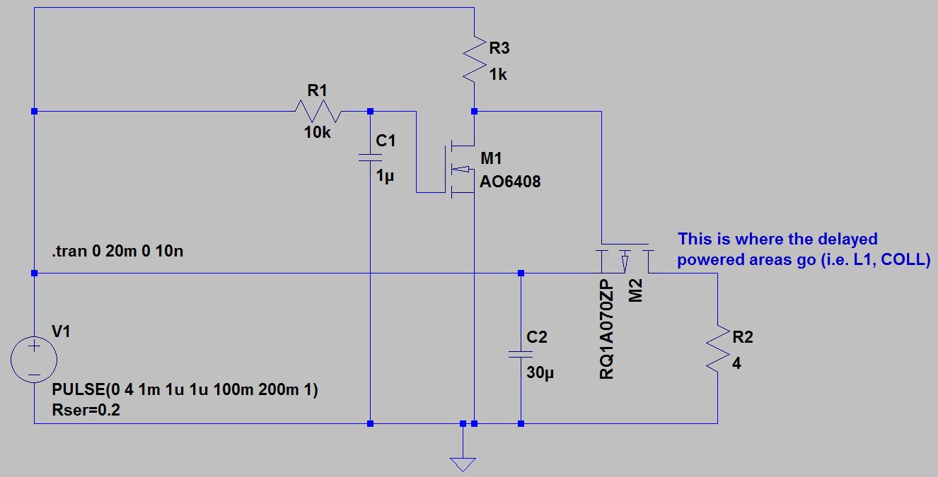
Here is one way to delay powering the sections that draw the larger current, allowing the unit to boot up before powering the final load. It's a little more complex than a simple soft-start, but should give you some wiggle room to optimize for your application.

enter image description here

\$\endgroup\$
1
  • \$\begingroup\$ Sorry, but I don't actually understand what goes where. \$\endgroup\$ Commented Jun 4, 2016 at 21:39
0
\$\begingroup\$

Try to put npn at the output so that 0.6V triggers it, and then collector pin to pin drive which should be connected via 200 ohm resistor to vcc, so that way you are only shutting down internal transistors

\$\endgroup\$
1
0
\$\begingroup\$

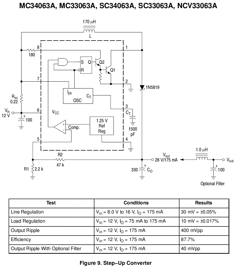
You forgot to use the MC34063 peak current limiting feature. You need to connect the main power to the Vin pin (6) and then it would need to go through a current sense resistor connected between Vin and Ipk (7) pins to the rest of the circuit. For 1A peak current you need a 0.3 Ohms resistor, and for the maximum peak current of 1.5A you need a 0.22 Ohms resistor. The formula for that resistor is: R_sense= 0.3 / i_pk

The ZXCT1109 chip is controlling your constant DC current, but not the peak current.

Below is an example boost circuit copied from the MC34063 datasheet.

MC34063 boost circuit design example

\$\endgroup\$

Your Answer

By clicking “Post Your Answer”, you agree to our terms of service and acknowledge you have read our privacy policy.

Not the answer you're looking for? Browse other questions tagged or ask your own question.