5
\$\begingroup\$

Is there any symbol for electrical insulation?

Is there any symbol for insulated wire? is there any symbol for non-insulated wire?

\$\endgroup\$
9
  • 1
    \$\begingroup\$ You mean like a symbol you would use on a schematic? I don't think so. But there are a lot of ratings and standards for wire and the type of insulation it has. You may see information printed on the insulation itself. \$\endgroup\$
    – user57037
    Commented Jun 1, 2016 at 6:11
  • 9
    \$\begingroup\$ Non-conductivity is indicated by whitespace. \$\endgroup\$
    – user207421
    Commented Jun 1, 2016 at 6:20
  • 2
    \$\begingroup\$ Do you mean how to call out a particular type of dielectric material on a mechanical drawing? An electronic schematic would not generally show insulation, it's implied everywhere there is not an explicitly shown connection. \$\endgroup\$
    – MarkU
    Commented Jun 1, 2016 at 6:22
  • 1
    \$\begingroup\$ Not much of an answer, but I have "solved" the issue in my schematics with a manual note next to the wire. \$\endgroup\$
    – winny
    Commented Jun 1, 2016 at 10:44
  • 1
    \$\begingroup\$ I fail to understand how this question is worth a bounty... \$\endgroup\$
    – dim
    Commented Jun 7, 2016 at 12:12

5 Answers 5

5
+200
\$\begingroup\$

Is there any symbol for electrical insulation?

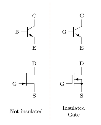
As mentioned in other answers, the answer is no, or better, the whitespace indicate non connection. You can see, for example, the difference between the gate in JFET (or base in BJT) symbol and the insulated gate in MOSFET and IGBT symbol. insulated gate
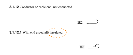
Is there any symbol for insulated wire? is there any symbol for non-insulated wire?

The only thing I can see in Standard is the following symbol: IEEE Std 315-1975 pag. 45
\$\endgroup\$
2
  • \$\begingroup\$ @ antonio I'm very much sorry that I did not visited the website within bounty period. \$\endgroup\$
    – user107801
    Commented Jun 28, 2016 at 13:55
  • \$\begingroup\$ @AlwaysConfused, don't worry. :-) \$\endgroup\$
    – Antonio
    Commented Jun 28, 2016 at 14:56
4
+50
\$\begingroup\$

No. A schematic diagram shows the logical interconnection of components. Whether any of the interconnections use insulated wire, or uninsulated wire, or a circuit board trace (or NO wire at all, for that matter) does not affect the actual CIRCUIT diagram.

Details like HOW components are interconnected are part of the NEXT step AFTER the schematic diagram: namely the IMPLEMENTATION or construction of the circuit.

\$\endgroup\$
1
  • \$\begingroup\$ It is not uncommon for schematics to mark places where stronger-than-normal insulation is required, e.g. by placing a dotted line between portions of the schematic on opposite sides of transformers or opto-isolators. \$\endgroup\$
    – supercat
    Commented Jul 5, 2016 at 17:43
4
\$\begingroup\$

Dotted lines around a conductive lines indicate shielding and full lines may indicate an enclosure. I am not aware of a symbol indicating insulation.

You can add a comment/text to indicate that this wire needs a particular insulation. That way you are certain that this critical information is visible in the schematics which is referenced more often than the design or repair manual that may accompany it in the future. Add information like voltage, thickness, kind of insulation material as you see fit [indicating voltage will help emphasize to the future reader that the insulation is indeed important].

\$\endgroup\$
4
  • 1
    \$\begingroup\$ I believe shielding in a wiring diagram is called out as a separate conductor pigtail. \$\endgroup\$
    – lm317
    Commented Jun 7, 2016 at 21:09
  • \$\begingroup\$ I have check several books I use for reference and other than in mechanical drawings, I did not find a representation for insulation. All four talk about insulators but only represent them in mechanical drawings. \$\endgroup\$
    – le_top
    Commented Jun 8, 2016 at 1:21
  • \$\begingroup\$ What about isolation barriers? A lack of connection between wires in a schematic implies a "normal" level of insulation between them, but some places require that certain things be especially-well isolated from each other. \$\endgroup\$
    – supercat
    Commented Jul 5, 2016 at 17:44
  • \$\begingroup\$ I've checked CRT schematics too - at best there is a warning triangle and some high voltage symbol but no specific symbol for insulation. \$\endgroup\$
    – le_top
    Commented Jul 5, 2016 at 20:38
0
\$\begingroup\$

The answer is no: no symbol for electrical insulation Because we study electronics and electricity which is the flow of electron in the conductor and semi-conductors

\$\endgroup\$
1
  • \$\begingroup\$ did you mean "no symbol for electrical insulation Because we study electronics" ? there is no different concept of insulation in electricals and electronics. In both "electricals" and "electronics" we use insulated wires.The term "electrical insulator" is the full-form of the term, because there are other-type of "insulators", such as "Heat-insulator" and "sound insulator". As well the name of this website is "stackexchange electrical engineering". And the border of electrical-engg, electronic-engg , and electrical-science, is very faint. \$\endgroup\$
    – user107801
    Commented Jul 20, 2016 at 9:29
0
\$\begingroup\$

It depends on if your talking about a cable diagram or a schematic diagram. Typically cables are not specified in schematic diagrams because there are connectors on the board. You can find and example of IEC or other standardized symbols here (you can also find examples of the IEEE symbols). You can look at the IEC standard if you want to buy it here. Even building schematics like the NEMA do not provide a cable symbol.

As far as cable diagrams most places do them in house and have there own markings for them. All of the cable diagrams I've encountered usually have a physical representation of the connector and or wire and then call out the material or part number if it is an order able item.

So do what makes sense, anything in a diagram that is atypical should be noted and that is up to the designer. The most important thing for diagrams:

  1. All information for the design is Documented
  2. That other people understand the diagram
\$\endgroup\$

Your Answer

By clicking “Post Your Answer”, you agree to our terms of service and acknowledge you have read our privacy policy.