1
\$\begingroup\$

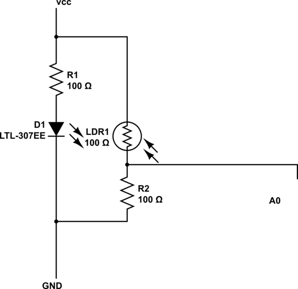
I have the following schematic.
schematic

simulate this circuit – Schematic created using CircuitLab

And it graphs to an almost stratight line. It is supposed to be a heartbeat sensor. From what I have read, I come to know that amplification is a must. But my knowledge of electronics is very limted and I need guidance.

I am emitting a red. My photoresistor responds to IR signal very poorly and I had to use the red one.

Am working with Arduino Uno board.

\$\endgroup\$
3
  • 2
    \$\begingroup\$ A term to research: instrumentation amplifier. Without more details, you're not going to get a more complete answer. \$\endgroup\$
    – The Photon
    Commented Jun 1, 2016 at 16:12
  • \$\begingroup\$ What is the actual voltage output range from your photoresistor circuit? How did you establish the value of R2? Where is the signal going? Does "A0" mean you are connecting it to an Arduino analog input pin? What are you trying to DO with the signal? Why do you think it needs amplification? \$\endgroup\$ Commented Jun 1, 2016 at 17:30
  • \$\begingroup\$ the signal is flat... it should have varied when my heart beats... \$\endgroup\$ Commented Jun 2, 2016 at 14:52

3 Answers 3

4
\$\begingroup\$

I suspect R2 is much too low; the 100 \$ \Omega \$ of the LDR is probably under high light condition, you probably have much less light.

I suggest empirically choose R2 to center the A0 point with nominal light. You may still need amplification, but this should give you the best performance without changing the topology.

\$\endgroup\$
1
\$\begingroup\$

Biological signals are generally very small (in the uV range). You should construct an amplifier of some sort. A instrumentation op-amp would do fine.

general info on instrumentation op-amps

Before you construct a circuit though you should have an idea about the signal. Get a good oscilloscope and you should be able to confirm you have a signal. It can be helpful to simulate a signal using a function generator rather than your heartbeat to test the circuit beforehand.

\$\endgroup\$
1
\$\begingroup\$

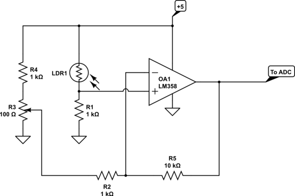
You can use a simple op-amp circuit (non-inverting configuration). No need for, or value in, an instrumentation amplifier.

Try this:

schematic

simulate this circuit – Schematic created using CircuitLab

Adjust R3 to get a couple volts at the output. If there is not enough range, reduce R1 a bit. This circuit gives 10x the voltage of yours (due to the 1K R1) and has a gain of +11, so 110 times the output. You can increase R5 to increase the gain further.

\$\endgroup\$

Your Answer

By clicking “Post Your Answer”, you agree to our terms of service and acknowledge you have read our privacy policy.

Not the answer you're looking for? Browse other questions tagged or ask your own question.