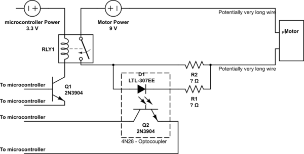
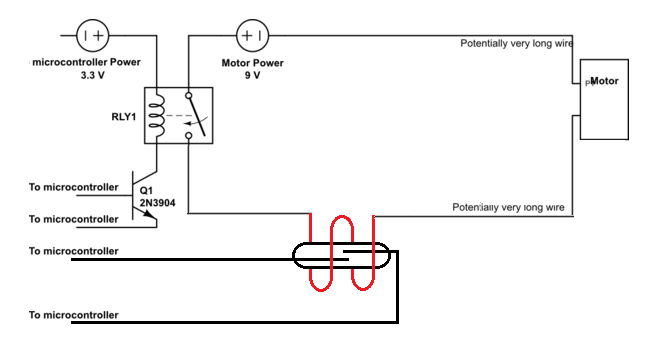
I'm trying to design a circuit where it is essentially a motor controlled by a microcontroller with some feedback. The motor will have its own isolated power supply and the actual on/off switch will be a relay + transistor.
What I'm looking for is to have some sort of feedback if the motor side is not working (power supply is dead or wire break, etc), as currently if the controller switches the transistor/relay, there is no way of telling if there is current going to the motor. The motor may also be far away (let's say a meter or two) as well, increasing the chance of a wire break.
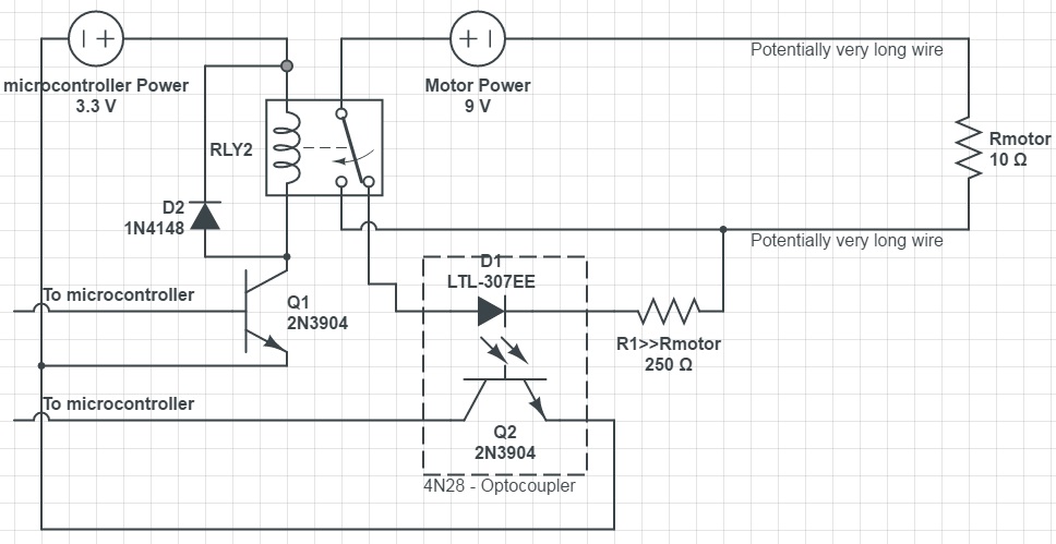
Currently, the only way I can think of doing this is to use an optocoupler with a current divider in parallel with the motor line. I have no idea if this a proper way, but I have gotten it to more or less work (with some guess work + trail and error on the resistor values). An issue is though that it is not perfect as I'm guessing when the motor is turned on/off (spinning up or spinning down or stall), the current draw changes which affects the reading a bit.
What would be a better/proper way to do this? Or what should I look up, as trying to search this in google just returns many results on how to measure current using a meter or using the continuity test.

simulate this circuit – Schematic created using CircuitLab
Side note: My knowledge in electrical engineering is pretty limited and my schematic is pretty rough just to get the idea across: I've omitted some parts, like the diode across the relay coil/motor and the transistor might be wrong one, etc.


