2
\$\begingroup\$

UPDATE

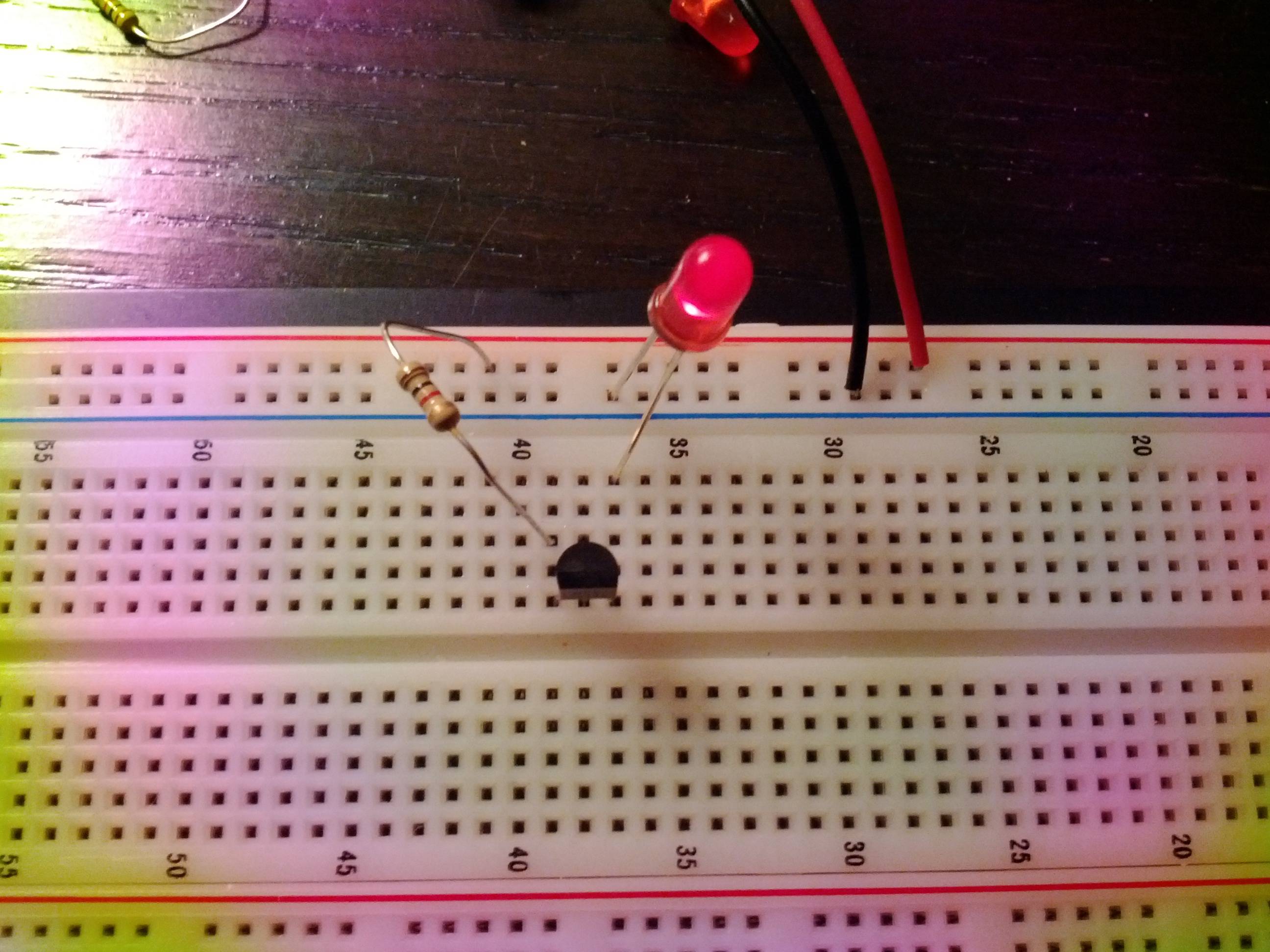
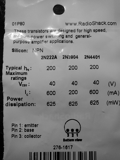
Have included an image. As you can see, LED is ON when base is floating. This is a 2N222A transistor.

enter image description here

enter image description here


Playing with an NPN bipolar transistor. The Collector is connected to the positive terminal of a 9V battery through a 1k Ohm resistor, and the Emitter is connected to the ground through an LED. The Base is not connected to anything.

The LED seems to be dim in the above case. When I connect the Base to the positive terminal, the LED is much brighter. That makes sense as current through the base Base amplifies the current.

My questions is: should any current flow through the emitter if the base is not connected to anything? I.e. Shouldn't the LED be completely off?

I have a similar question for NPN Unijunction transistors (understand that nomenclature changes from CBE to AGC)?

\$\endgroup\$
11
  • \$\begingroup\$ Are you limiting current through the base when you connect it to the positive terminal? (i.e. are you connecting it directly or through a resistor?) It's possible the transistor is damaged if you connected it directly. Also, instead of leaving the base not connected, connect it to ground to turn off. \$\endgroup\$
    – Oli Glaser
    Commented Dec 21, 2011 at 3:26
  • 1
    \$\begingroup\$ @Faken - no it shouldn't matter, it should be off with base floating - the base to ground was just to "make sure" in case there was something not mentioned going on. \$\endgroup\$
    – Oli Glaser
    Commented Dec 21, 2011 at 4:05
  • 1
    \$\begingroup\$ @Faken - Just to add to the grounded base answer for detail: It is possible to get reverse CB leakage that can be amplified and turn the transistor on very slightly, especially at higher temperatures. It shouldn't be an issue here though, I was thinking more of a pullup that hadn't been mentioned or something similar. \$\endgroup\$
    – Oli Glaser
    Commented Dec 21, 2011 at 4:21
  • 1
    \$\begingroup\$ You need to stip playing randomly and start with a circuit that is "correct". You comment "It seems weird ..." should be replaced with "I don't know enough to undersand why ..." See end of my answer. \$\endgroup\$
    – Russell McMahon
    Commented Dec 21, 2011 at 4:31
  • 1
    \$\begingroup\$ Please answer: - What colour LED are you using? - What is your transistor type. ? \$\endgroup\$
    – Russell McMahon
    Commented Dec 21, 2011 at 4:35

2 Answers 2

2
\$\begingroup\$

Okay, looking at the picture I think you may have the transistor the wrong way round.

Try turning it round.

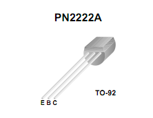
See this picture for reference:

enter image description here

As you can see the collector is on the right with the flat part facing you, so you have the collector connected to the LED in your circuit (if the 2N2222A part you are using has the same pinout)
I got the picture from here.

EDIT - It's actually a 2N222A, but the above advice still goes as the pinout appears to be the same from the picture posted.

As Russell mentions the more standard way is to connect the LED to the collector, but your circuit should work if set up correctly.

\$\endgroup\$
6
  • \$\begingroup\$ Sorry at OliGlaser I meant it's a 2N222A transistor (previously wrote 2N2222A). \$\endgroup\$ Commented Dec 21, 2011 at 4:28
  • 1
    \$\begingroup\$ Ah okay - I think it's still wrong though, as the additional picture you added shows the pins as if you are looking at the bottom of the transistor. \$\endgroup\$
    – Oli Glaser
    Commented Dec 21, 2011 at 4:40
  • \$\begingroup\$ +1 Your absolutely right. Test now works. On another note: Does it makes sense that for the LED to be dimly lit if the base is connected to the positive terminal and the collector is floating? \$\endgroup\$ Commented Dec 21, 2011 at 4:54
  • 2
    \$\begingroup\$ Don't you mean the base floating but the emitter/collector swapped? If so, then yes it does make sense. The leakage from the reverse biased EB junction will be probably much larger than if the transistor is connected the right way round. An NPN transistor can be made to work badly in reverse, this is probably what you were seeing. Usually, anything outside the recommended operating conditions can be generally considered to have "undefined" results. \$\endgroup\$
    – Oli Glaser
    Commented Dec 21, 2011 at 5:01
  • \$\begingroup\$ If you did mean the collector floating then the LED being lit also makes sense as the current should flow straight through the BE junction and through the LED to ground. \$\endgroup\$
    – Oli Glaser
    Commented Dec 21, 2011 at 5:03
1
\$\begingroup\$

Please answer:

  • What colour LED are you using?

  • What is your transistor type. ?


You should look at some of the 10's of thousands of diagrams available on the net before connecting a transistor to try to do this job and/or look at the transistor's data sheet.

All transistors have a maximum Vbe rating and you have probably exceeded yours quite substantially. You transistor MAY be OK but may be damaged.

You MAY have been saved by your interesting emitter follower style circuit.

As a starting point always drive the base through a resistor of from 1k to 10k.
1K for low voltages (2-5) and 10k or so for larger voltages (5-30).
None of that is ideal but it will keep your transistor alive and your LED lit in most cases.

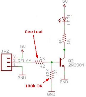
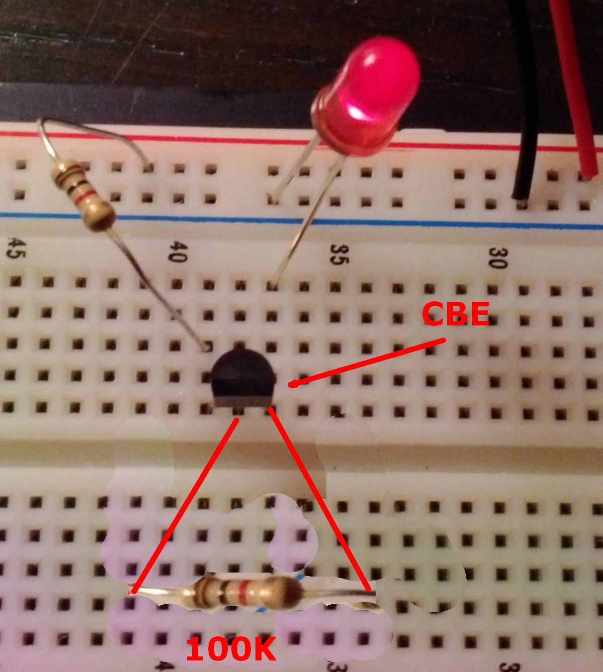
Connect a 100k from base to emitter. This passes the small CB leakage current that exists when the base is open and stops it driving the transistor on partially and dimly lighting your LED.

Your circuit with the LED in the emitter has its uses, but more usual and useful is the circuit below.

R1 is not needed if you are driving R2 with a source that always has a low impedance, such as a microcontroller pin in normal output mode (active high and active low drive.

Transistor type is your choice.

LED current is ~~~= (Vsupply - VLED_on)/ R4.
VLDon from data sheet or elseweher.
For red LEDs ~= 2V.
White and blue LEDS typically 3V - 3.5V

So here with Vsupply = 5V

  • LED current is ~~~= (Vsupply - VLED_on)/ R4
    ~~= (5 - 3.3) / 1000 = 0.017 = 17 mA

This is shown being driven by a relay (high on / low off) but any voltage that switches between low ~=0V and 2V <= high <= ~= 12v is OK.
For Vin high > 12 V increase R2.


Suggestion:

Experiment with vakues of R2 all else being the same, and see what happens. .
Never have R2 < about 500 ohms.
R2 can be as large as you like but the LED will stop working when R2 is above about 470k to 1 megohm.
enter image description here


Recommendation:

The BC337-40 is my favorite leaded "jellybean" bipolar NPN transistor.
If you can ever buy some of these at a good price, do.

Digikey has them at 58 cents in 1.s, 40c/10, 18c/100, 7c/1000, 4.5 cents/ 10k.


This is a BAD circuit BUT if you add 100K as shown the LED should turn off.

NOW connect 10k from base to V+ and see what happens.

NEVER connect the base directly to V+ or to any "stiff' voltage source that may cause very high base currents to flow.

What is your transistor type. ?
enter image description here

\$\endgroup\$
5
  • \$\begingroup\$ That's not all I said. Just changing the resistor is pointless. If you build the circuit described in my answer you will be MUCH better off. \$\endgroup\$
    – Russell McMahon
    Commented Dec 21, 2011 at 4:36
  • \$\begingroup\$ I appreciate that and will try the circuit in your diagram, but I'm just trying to do a proof of concept of how a transistor works as someone who is completely new to Electrical Engineering. Can't that be shown in a simple circuit? Why do relays have to be involved to show how a transistor works? \$\endgroup\$ Commented Dec 21, 2011 at 4:42
  • \$\begingroup\$ +1 Thanks for the helpful comments. I will try out the circuit you mentioned above. \$\endgroup\$ Commented Dec 21, 2011 at 4:50
  • \$\begingroup\$ @Tuva The "relay" label appears to be an error, it looks like just a generic power/signal input header probably borrowed from another circuit that was using it for something to do with a relay. \$\endgroup\$ Commented Dec 21, 2011 at 6:05
  • \$\begingroup\$ If you read and understand the text you will understand the relay stuff. It says: This is shown being driven by a relay (high on / low off) but any voltage that switches between low ~=0V and 2V <= high <= ~= 12v is OK. \$\endgroup\$
    – Russell McMahon
    Commented Dec 21, 2011 at 6:11

Your Answer

By clicking “Post Your Answer”, you agree to our terms of service and acknowledge you have read our privacy policy.

Not the answer you're looking for? Browse other questions tagged or ask your own question.