0
\$\begingroup\$

I am trying to breadboard a DC circuit schematic (a sawtooth voltage controlled oscillator, to be precise). In the schematic there is a positive supply, a negative supply and ground (+4.5V, -4.5V and a ground, respectively).

I understand some things about the potential difference and the reference voltage. I tried to connect every pin which in the schematic is connected to the ground, with the negative supply. But I am sure that is not correct. I did a bit of research and now I know that the potential voltage difference between the positive and negative supply must be 9V and the ground is in the middle of this difference.

The problem is, I have a power supply device that has only Positive and Negative supply. So, what do you propose I do? I do not feel that it is correct to connect to the ground, every pin connected in the negative supply in the schematic. I am sorry if this exact question is asked again, but I am searching everywhere, even in stack exchange for over an hour now. Thank you in advance.

\$\endgroup\$
7
  • \$\begingroup\$ GND is the arbitrary point in a schematic we assign 0V to. \$\endgroup\$
    – PlasmaHH
    Commented Jul 4, 2016 at 11:32
  • 3
    \$\begingroup\$ I propose you get the power supply which suits the circuit you have. A +4.5V/-4.5V PSU is different from a +9V one. \$\endgroup\$ Commented Jul 4, 2016 at 11:35
  • 3
    \$\begingroup\$ Show us your schematic diagram and someone may have a workaround for you. \$\endgroup\$
    – Transistor
    Commented Jul 4, 2016 at 11:36
  • \$\begingroup\$ Well, the schematic is this: electronicdesign.com/site-files/electronicdesign.com/files/… As you can see, it has both a negative supply and ground. I can simulate it in Spice just fine. But in the "real world" I have a power supply which doesn't include a ground pin. I tried connecting to my negative supply, all the components that are connected to the ground along with the ones that are connected to the negative supply... But I do not feel this is the right answer. Any ideas? \$\endgroup\$ Commented Jul 4, 2016 at 11:40
  • \$\begingroup\$ "I tried to connect every pin which in the schematic is connected to the ground, with the negative supply." Ground and the negative supply are not the same thing. Only connect points clearly marked as negative (e.g. -5V) to the negative supply. You need to get a power supply with +5V, ground and -5V. \$\endgroup\$
    – tcrosley
    Commented Jul 4, 2016 at 11:41

2 Answers 2

1
\$\begingroup\$

You need to provide both plus and minus 5 volts (not 4.5) for the schematic you provided.

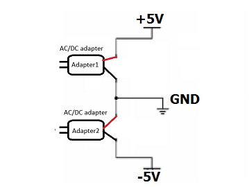
Bipolar power supplies can be expensive, but you can fake one using two 5V "wal-warts" connected in series:

enter image description here

Then just connect the +5V, -5V and ground nodes in the schematic to the respective outputs shown above. As you can see now, -5V and ground are not the same.

Note: you can also do the same thing with two sets of batteries connected in series; the circuit may work okay with 4.5V, in which case you could use three AA or AAA cells in series for the top compound battery, and another three cells for the bottom one.

\$\endgroup\$
9
  • \$\begingroup\$ Oh nice. I understand now. I have a new question now, though. Is it possible to "fake" two power supplies by using only one? For example, I have a transformer with two pins: + and -. Can I connect the positive one to the positive power supply rail, the negative one to the negative power supply rail and from there connect with wires both the positive and negative rail to a new one, and thus create a ground? \$\endgroup\$ Commented Jul 4, 2016 at 11:59
  • \$\begingroup\$ Sort of, like having only one AC/DC adapter and connectinv its + pin to two points in the schematic you just posted and its - to the other two points. Is it possible? Sorry if this is a noob question. \$\endgroup\$ Commented Jul 4, 2016 at 12:00
  • 1
    \$\begingroup\$ No, that won't work. Connect as shown in my diagram. \$\endgroup\$
    – tcrosley
    Commented Jul 4, 2016 at 12:00
  • \$\begingroup\$ So, if I manage to get my hands on a transformer that has a +5V and a ground and given that I already have a power supply with +5V and -5V, is it possible to create what I need? \$\endgroup\$ Commented Jul 4, 2016 at 12:10
  • \$\begingroup\$ There is no such thing as a power supply with just +5V and -5V (without a ground), what you already have is one with +5V and ground. Then add the second one as shown in my answer. I hope you mean "power supply" and not just "transformer", they are not the same thing. \$\endgroup\$
    – tcrosley
    Commented Jul 4, 2016 at 12:13
1
\$\begingroup\$

As PlasmaHH said,

GND is the arbitrary point in a schematic we assign 0V to.

You then need two power supplies, each one generatong 4.5 V. You connect the positive terminal of the first one to the +4.5 V node in you circuit and the negative terminal to GND. Then, you connect the positive terminal of the second one to the GND node in you circuit and the negative terminal to the -4.5 V node.

\$\endgroup\$

Your Answer

By clicking “Post Your Answer”, you agree to our terms of service and acknowledge you have read our privacy policy.

Not the answer you're looking for? Browse other questions tagged or ask your own question.