1
\$\begingroup\$

I've started to build a brushless driver by using some Power MOSFETs and some MOSFET drivers, in order to drive the Power MOSFETs.

I have connected the chips as shown in the application circuit (page 3) in the datasheet of the L6743D MOSFET driver, in order to drive my couple of N-MOSFET, but I noticed that nothing worked as it should.

After that, I decided to check if the MOSFET Driver (L6743D) is working as it should. Therefore I have powered up the L6743D with 12 V Vcc, set High the EN pin (5 V of the micro) and set the PWM input from my micro (Arduino).

At this point I noticed that the UGATE pin keeps staying HIGH (constant at Vcc = 12 V), while the LGATE is following the PWM signal's shape.

According to the datasheet listed above (page 8), the UGATE pin should be the opposite of the LGATE pin. Hence I should have something similar to my PWM signal given as input and both the signals should turn on/off the Power MOSFETs.

This is not happening and I really don't understand what I'm doing wrong.

Could you help me, please? Am I missing something about the usage of the L6743D MOSFET Driver?

Thank you in advance for your help!

EDIT

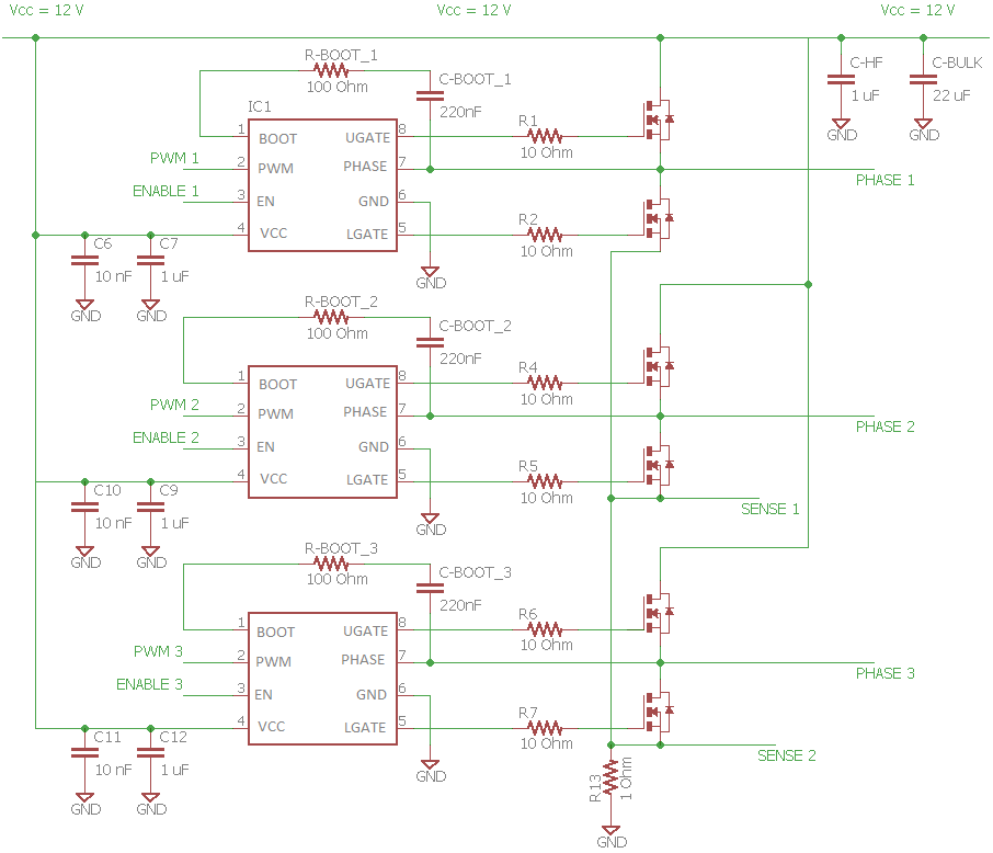
Here you are my circuit, consider the couple of N-MOSFETs into the same package.

enter image description here

When I turn on the power supplier and limit the current to 200mA, the power supplier shows me that there is a CC. I have also tried to set the limit higher without any success.

Hope this is helpful to understand my issue.

\$\endgroup\$
7
  • 1
    \$\begingroup\$ Post a picture of your circuit construction. \$\endgroup\$
    – pgvoorhees
    Commented Jul 5, 2016 at 15:03
  • \$\begingroup\$ When you did your test, where did you connect the PHASE pin? The High-Side driver output UGATE uses PHASE as its 'low' output value, so you can't leave it floating. \$\endgroup\$
    – brhans
    Commented Jul 5, 2016 at 15:15
  • \$\begingroup\$ What is your bootstrap capacitor and resistor value and PWM frequency? \$\endgroup\$ Commented Jul 5, 2016 at 15:49
  • \$\begingroup\$ I've posted the circuit schema above. The frequency of my PWM is around 500 Hz, but I can take it to 10 KHz if needed. \$\endgroup\$
    – starScream
    Commented Jul 5, 2016 at 19:04
  • \$\begingroup\$ To expand on @brhans comment: When you measured the voltage on UGATE, did you measure it with respect to GND? or with respect to PHASE? Were the MosFETs attached? You need to measure UGATE with respect to PHASE, and you need the lower MosFET to turn on in order to charge the bootstrap capacitor. \$\endgroup\$
    – Mark
    Commented Jul 5, 2016 at 19:48

1 Answer 1

1
\$\begingroup\$

Belay the answer below! Thanks for the clarification of your application. The answer is appropriate for a buck converter. Your problem is that this chip is designed for the buck converter and not a brushless motor, so you will have to play some tricks if you want to try to make it work. You would have to use the enable signal to disable one of the drivers for the open phase, leave the low side driver on for the low side phase and perform PWM on the high side using either the enable pin of you want the phase open for PWM, or use the PWM input if you want to take the high side to ground for PWM. You still have to follow the rules for a bootstrap capacitor.

Chances are your PWM signal frequency is not high enough, or your bootstrap capacitor is not large enough. When the low side FET turns on, it pulls down the low side of the boot capacitor charging the capacitor to 12 volts in your case. Then when it is released its charge pumps up the BOOT input, so it needs enough charge to provide a voltage that will be higher than Vcc so that you can turn on the HS FET. Remember that to turn on the high side FET, the gate must have a voltage greater than the source, so you must have a voltage on this capacitor greater than 12 volts with respect to ground (greater than the voltage on PHASE). The charge pump can only charge the cap when the PWM transitions occur, so if the transitions are too infrequent (low frequency) and/or if the boot capacitance is too small (not enough charge), you won't be able to maintain your high side voltage and the HS gate will not remain above 12 volts. It's a little confusing in the data sheet because the low side gate voltage waveform is measured with respect to ground, which is a direct scope reading, but the high side voltage is measured with respect to its source (the PHASE signal), so it won't look like the signal in the timing diagram but will follow PHASE up and down.

\$\endgroup\$
6
  • \$\begingroup\$ Thank you for your answer @John! Could you suggest something else which is allows me to drive my couple of MOSFETs easier, please? And furhteremore, do you think there are any better power MOSFETs than what I've posted? Are they ok for driving 3 Phase BLDCs? \$\endgroup\$
    – starScream
    Commented Jul 6, 2016 at 20:41
  • \$\begingroup\$ You can use the circuit as is if you have the right logic. To run the motor with PWM, you need one motor phase open, one high and one low. The PWM signal switches the output from high to low on this device, and the enable pin makes it open circuit regardless of the PWM input. You can have one phase open (using enable to turn it off), one phase low (enable on and PWM input low) and one phase high with motor PWM (using PWM input for high and enable to turn it on and off). Use the high side for motor PWM so you can keep your cap charged. \$\endgroup\$ Commented Jul 6, 2016 at 21:40
  • \$\begingroup\$ Hence my circuit schema should be fine, am I correct? Furthermore, what do you mean with PWM LOW for the motor phase LOW, do I have just to set it to 0 V? And by saing PWM input for high and enable to turn it on and off do you mean that I should apply the PWM signal to the PWM input pin as constant, and turn the driver ON and OFF by using the ENABLE pin? \$\endgroup\$
    – starScream
    Commented Jul 14, 2016 at 20:53
  • \$\begingroup\$ That is correct. \$\endgroup\$ Commented Jul 15, 2016 at 13:15
  • \$\begingroup\$ Thank you!! Could you suggest me a commutation sequence, please? It's really tricky understanding how to do that. \$\endgroup\$
    – starScream
    Commented Jul 15, 2016 at 13:40

Your Answer

By clicking “Post Your Answer”, you agree to our terms of service and acknowledge you have read our privacy policy.

Not the answer you're looking for? Browse other questions tagged or ask your own question.