0
\$\begingroup\$

I am currently working on a project where we have to pilot the command of a machine via a remote control based on some input.

Normally, the remote control is a simple push button but we are working on making this push button to be activated based on some logic, hence we need a mcu to send a signal to the machine to simulate a push button which is normally mechanic.

We are currently designing the remote control schematic and PCB but first we have a small doubt on one point:

The machine user manual mention this:

The remote is a normally open SPDT switch connected to the machine with a 1/4 inch stereo phone jack. The sleeve contact of the phone jack is at common, the tip contact is the normally open signal PCA*. The jack is metal threaded and bulkhead mounted on the rear of the device. A harness connects the jack to the MCU PWA with a 4 pin, locking, polarized connector.

Activation of the switch results in signal PCA going low as long as the switch is held. The third signal PPP*, is low if the cable is connected and the pendant is not pressed. This provides positive identification of a correct and functioning remote control

A few questions:

  1. Should we rather use a relay or an octocoupler to simulate this SPDT switch ?
  2. I don't very well understand what they mean by "The sleeve contact of the phone jack is at common, the tip contact is the normally open signal PCA". How do you understand this ?

EDIT: the asterisk lead nowhere.

\$\endgroup\$
8
  • \$\begingroup\$ What is 'PCA' and 'PPP' which are asterisks but never explained? Why is PPP the third signal and how does this relate to the first and second signals (which you fail to identify as such? Is PPP the middle connection of the jack plug which is connected LOW when the switch is not pressed and goes HIGH (or open circuit? - please clarify which) when it is? BTW its optocoupler not octocoupler. I'm certain if you simply did a sketch of a 3.5mm jack plug and labelled it you'd answer question 2 for yourself. (common is usually another way of saying ground or 0V) \$\endgroup\$ Commented Jul 19, 2016 at 9:47
  • \$\begingroup\$ @JImDearden, the asterisks lead nowhere, reason why I am asking As from my understanding I suppose "PCA" mean Principal component Analysis but no idea what is PPP \$\endgroup\$
    – chris
    Commented Jul 19, 2016 at 9:52
  • \$\begingroup\$ en.wikipedia.org/wiki/Switch#Contact_terminology \$\endgroup\$
    – JimmyB
    Commented Jul 19, 2016 at 9:54
  • \$\begingroup\$ "Should we rather use a relay or an octocoupler to simulate this SPDT switch ?" - If you don't know anything else about the circuit (voltage, polarity, current) you really should use a relay. \$\endgroup\$
    – JimmyB
    Commented Jul 19, 2016 at 9:56
  • \$\begingroup\$ To me, it looks like PCA and PPP are defined just there. PCA is the push button, normally open, connected to "common" a.k.a. "low" when activated. PPP "is low if the cable is connected and the pendant is not pressed", so it's just the inverse of PCA, i.e. the other contact of the SPDT. \$\endgroup\$
    – JimmyB
    Commented Jul 19, 2016 at 9:59

1 Answer 1

1
\$\begingroup\$
  1. You can use a sealed signal relay (< 2A) such as an Omron G6. There are other options, but the relay is straightforward and should just work.

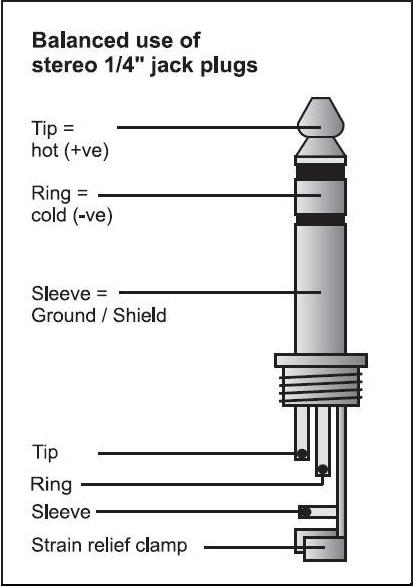
  2. A 1/4" stereo plug has three electrically isolated parts- the tip, the ring and the sleeve (image from this site, ignore the balanced, hot/cold designations).

enter image description here

It's not entirely clear from the verbal description how the switch is to be connected other than that the N.O. contact goes to the tip. I could make an educated guess (N.C. to ring and common to sleeve), but it would be much better to get even a hand scrawled schematic from the supplier.

\$\endgroup\$

Your Answer

By clicking “Post Your Answer”, you agree to our terms of service and acknowledge you have read our privacy policy.

Not the answer you're looking for? Browse other questions tagged or ask your own question.