0
\$\begingroup\$

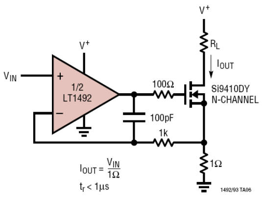
I want to create an AC load for testing high capacity battery (200Ah) using the circuit below: enter image description here

Can I put an AC voltage at Vin and get a AC load current through the FET? And why do they need LT1492 with 55mA output current capability while the FET gate current is micro-Amp small?

Another thing that trouble me is that why Iout only depend on that 1 Ohm resistor and not RL?

V+ is connected to the battery.

\$\endgroup\$
5
  • \$\begingroup\$ What frequency will your 'AC' signal be? The FET's gate current for a DC gate voltage is very small but the gate has a significant capacitance, so the op-amp needs to be able to supply enough current to charge and discharge it through the 100 ohm resistor in order to meet the sub-1µs rise-time specification in the circuit you've posted. If you don't need that speed of response you can get away with a lower current. \$\endgroup\$
    – nekomatic
    Commented Jul 21, 2016 at 10:13
  • \$\begingroup\$ Well, my AC signal is around 1kHz and I need about 1.5A to 2A through the FET and load resistance. Can a 16mA TLV2370 handle this current? \$\endgroup\$
    – kingyo
    Commented Jul 25, 2016 at 2:16
  • \$\begingroup\$ A good answer to that question is beyond my knowledge level but a quick check of the Si9410DY datasheet shows a maximum gate charge of 50 nC, and a current of 16 mA delivers that charge in just over 3 µs, which is small compared with the interval of 500 µs between switch on and switch off at 1 kHz. The actual current won't be constant but will decay exponentially as the gate charges through the 100 ohm resistor, which you may want to increase in order to limit the current to what the op-amp can handle, but even if we assume a factor of 10 longer as a rough approximation… \$\endgroup\$
    – nekomatic
    Commented Jul 25, 2016 at 8:24
  • \$\begingroup\$ …you've still turned the FET on or off within about 30 µs. So my guess is it'll work OK, but the FET is going to spend some time in partial conduction as the gate voltage rises or falls and that means it will need to dissipate some heat - that's the limiting factor, aside from any spec you want to place on how fast the current must rise or fall for your application. \$\endgroup\$
    – nekomatic
    Commented Jul 25, 2016 at 8:27
  • \$\begingroup\$ See for example electronics.stackexchange.com/questions/31594/… and electronics.stackexchange.com/questions/107858/… \$\endgroup\$
    – nekomatic
    Commented Jul 25, 2016 at 8:29

1 Answer 1

2
\$\begingroup\$

The circuit is an op-amp with ground as the negative rail. This means Vin cannot go below the negative rail. Now look at the output current formula - it involves Vin and, if Vin cannot go below ground, then the current through the MOSFET HAS to be positive only.

In short, you cannot put an AC voltage at Vin unless it is biased to make its most negative excursion higher than ground and this of course means you CANNOT get an AC load current through the MOSFET. At best it will be an AC load current superimposed on a DC load current whose most negative current is still slightly positive with respect to the Iout arrow in the picture.

Another thing that trouble me is that why Iout only depend on that 1 Ohm resistor and not RL?

Because the op-amp sets the voltage across the 1 ohm resistor by appropriately driving the MOSFET to equal Vin. This means that Iout MUST equal Vin/1ohm. This is bread-and-butter for an op-amp operating linearly.
\$\endgroup\$
2
  • \$\begingroup\$ Thanks Andy, what I meant by "AC current" is exactly as you've described, I just didn't have any other words to talk about it :). Now, LT1492 price is a little bit too high to my application, can I use a lower power general purpose op-amp instead? OPA237 seems like a pretty good alternative with 8mA output. \$\endgroup\$
    – kingyo
    Commented Jul 21, 2016 at 9:57
  • \$\begingroup\$ It will probably be OK (input common mode range includes ground and output can swing to very nearly ground) for most applications like this but you can always simulate it in something like LTSpice (free software). \$\endgroup\$
    – Andy aka
    Commented Jul 21, 2016 at 10:02

Your Answer

By clicking “Post Your Answer”, you agree to our terms of service and acknowledge you have read our privacy policy.

Not the answer you're looking for? Browse other questions tagged or ask your own question.