5
\$\begingroup\$

I am designing a 4 layer PCB with power planes and a ground plane, with mixed voltage signals and high currents. I have two possible isolated ground plane configurations, and I am wondering which would be better in terms of reducing EMI and noise. The logic circuit includes a microcontroller with ADCs, so I don't want the high current ground to interfere with the analog signals. The power section drives a motor, so the ground there will be very noisy. Here are my power planes. enter image description here
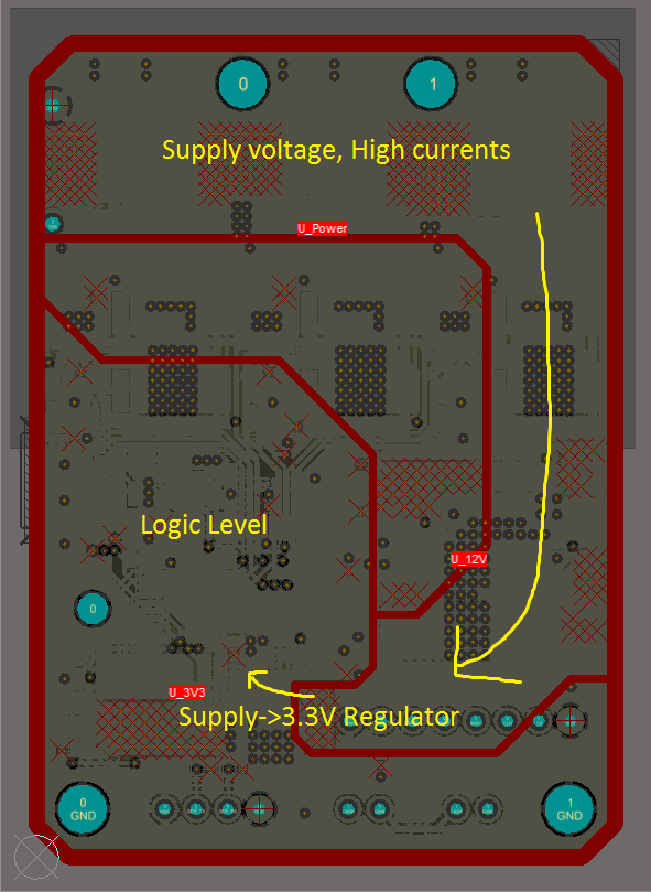
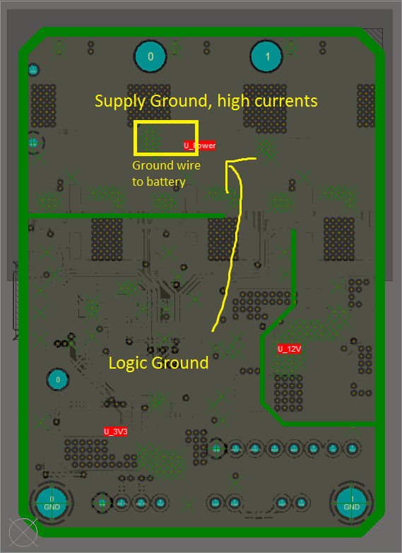
One of my ground plane configurations forces the logic level ground return path to follow the same path as the supply path to the regulator. For this configuration, I am assuming that it is better for the logic ground currents to return to the regulator's ground pin. The advantages I can see are that the current will return in the same path as the supply, so there is no inductance created by current loops. The isolation from the high current ground also seems to be better (not sure if this is true). enter image description here

The other ground plane configuration allows for a more direct current path from the logic ground to the supply ground for minimal resistance (instead of the regulator's ground), but it creates a larger current loop. It also seems to be less isolated from the high current ground (again not sure about this). enter image description here
Which ground plane configuration would be better for EMI and signal integrity, and why? In general, if I have a regulator, should the ground return path be optimized to return to the ground of the regulator (and then back to the supply ground), or straight back to the supply ground?

\$\endgroup\$

2 Answers 2

4
\$\begingroup\$

This sounds odd -- but try not partitioning your ground plane. Instead, make sure that the components and traces for a given subsystem (logic, analog, digital) all stay in their respective areas instead of "spilling over" with high-speed digital traces running through analog circuits for instance. Ground plane currents will take the lowest impedance path back to the source, which at high frequencies follows the trace they are the return for.

\$\endgroup\$
1
  • 1
    \$\begingroup\$ The key on this "respective areas" is to make sure your sensitive circuitry is not between a noisy load and the power supply. In that instance the noisy return currents want to go through the analog circuitry. \$\endgroup\$
    – Barleyman
    Commented Jul 22, 2016 at 10:01
3
\$\begingroup\$

If your goal is reducing EMI and noise you probably don't need a split ground plane. The split plane is typically done when you have sensitive analog devices (e.g. ADCs) and you want them to have a clean ground reference. It's better to avoid partitioning the ground plane.

High frequency return currents will follow a reference plane – they might use a power plane for return, especially for traces on whatever side of the board is closer to the power plane (often the bottom layer in 4-layer boards). For this reason it's important to make sure high frequency digital traces follow a continuous reference plane. If you partition ground, you must ensure no trace ever crosses the gap, making the routing harder as the board gets more constrained.

If a trace cross a partition in the ground plane, the return current will go the long way around. If a trace crosses a gap between power planes and is using the power plane to return, it may go on a long tour of your board to find a high frequency route between two disconnected power planes. See my answer here on high frequency routing.

As usual Henry Ott has good advice as well.

\$\endgroup\$
4
  • \$\begingroup\$ I do have ADCs on the microcontroller on my logic level circuit, so I didn't want the supply ground noise to affect it. I don't think I have high frequency signals on my logic level circuit, only a crystal for the controller and some 20 kHz PWM signals. The regulator is a 600kHz buck converter. Is this a good justification for splitting ground? If so, is it better for the ground return to follow the original path or straight to the source, if I don't have significantly high frequency signals? \$\endgroup\$ Commented Jul 22, 2016 at 1:56
  • 2
    \$\begingroup\$ Microcontroller ADCs are normally low resolution and don't usually have to deal with this -- other sources of noise in the microcontroller are usually bigger. In any case: if you correctly keep the analog and digital signals tracks separated, their return paths on the ground plane will follow suit and the ground plane split is not usually needed. If you don't keep them separate, a ground plane split will make things worse by forcing return paths to make large loops. Split ground planes are sometimes useful, but consider that "advanced" \$\endgroup\$
    – Evan
    Commented Jul 22, 2016 at 4:14
  • \$\begingroup\$ @RaphaelChang I agree with Evan. A split ground plane is probably overkill for a low frequency, low resolution design. \$\endgroup\$
    – jbarlow
    Commented Jul 22, 2016 at 5:42
  • \$\begingroup\$ @Evan 12-bit ADC is plenty sensitive enough to require careful conditioning. I've done my share of sensor circuitry and in some cases the split definitely serves it's place. But then you have to be religious about minding your return current paths. You can cross "the gap" .. Provided you provide an analog return ground "island" on adjacent layer. One of the easiest ways to gap things is to make an u-shape gap around the ADC/amplifier circuit which will make low-frequency ground currents go around the circuit without overtly complicating things. \$\endgroup\$
    – Barleyman
    Commented Jul 22, 2016 at 9:59

Your Answer

By clicking “Post Your Answer”, you agree to our terms of service and acknowledge you have read our privacy policy.

Not the answer you're looking for? Browse other questions tagged or ask your own question.