1
\$\begingroup\$

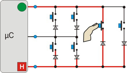
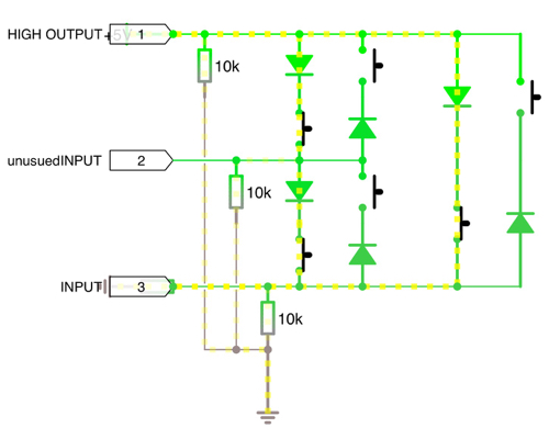
I'm using an Arduino Nano to make some sort of "console" and I'm currently designing the controller. However, I would like at least two of them with 6 buttons each. I have reserved 4 pins for the VGA output so there simply aren't enough pins.

The controller only consists of the 6 buttons, with a cable going back to the arduino. The cable must include power and ground. I have considered using radio but that's out of scope for me at the moment.

\$\endgroup\$
7
  • \$\begingroup\$ That's a 3x4 matrix. You need seven pins or external circitry like an I2C multiplexer. \$\endgroup\$
    – winny
    Commented Jul 23, 2016 at 10:38
  • \$\begingroup\$ Does the nano include an ADC? Do you need buttons to be pressed simultaneously? If yes, how many? \$\endgroup\$ Commented Jul 23, 2016 at 10:42
  • \$\begingroup\$ The nano includes several analog pins(If thats what you mean) and yes, i would like them to be pressed simultaneously. \$\endgroup\$
    – James Pae
    Commented Jul 23, 2016 at 10:45
  • \$\begingroup\$ and how many bits do you have? 8 bits should be enough. I am writing an answer though. \$\endgroup\$ Commented Jul 23, 2016 at 10:49
  • \$\begingroup\$ @VladimirCravero Unsure, But it uses a ATmega328. \$\endgroup\$
    – James Pae
    Commented Jul 23, 2016 at 10:52

4 Answers 4

6
\$\begingroup\$

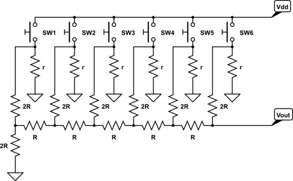
You could use the good, old, R2R DAC:

schematic

simulate this circuit – Schematic created using CircuitLab

All r should be small enough wrt to R to pull down the push button output when it is released. Some good values you can start with are:

  • \$r=1k\Omega\$
  • \$R=47k\Omega\$
  • \$2R=100k\Omega\$

Better yet, use one \$100k\Omega\$ resistor for R and two of them in series for the 2R resistor.

I will not dig in how this circuit works, refer to wikipedia for an explaination, what you want to know is that if we associate a digital number to the push button states, the output voltage is an analog representation of such number.

If the button is pressed, we say it is 1, if it is not pressed we say it is 0. SW1 is the LSB, i.e. the rightmost bit, while SW6 is the MSB, i.e. the leftmost.

As an example, if you press SW6, 3 and 2 the digital number is \$D=100110\$, which in decimal is 38.

The output voltage depends on \$V_{dd}\$ and is: $$ V_{out}=V_{dd}\frac{D}{2^N} $$ where N is the number of switches, in this case 6.

You can sample the analog voltage with the arduino ADC and then convert it back to a digital representation of the status.

Since you have an eight bit converter, the routine will be pretty neat:

uint_8t sw_status;
while(1) {
  sw_status = adc_read() >> 2;
  // do something with sw_status. the lsb represents SW1, and so on, e.g.:
  if (sw_status & (1 << 3)) {
    //SW3 is pressed here!
  }
}

There are some problems with this. First of all, you need precise resistors, or you will get non monotonic behavior which is very bad. The ADC on the nano should be precise enough, but you need to check if it accepts rail to rail inputs. And you get some error because you do not have SPDT push buttons, and you need to use the pull down. Moreover, if you have long wires going to the console, you will probably need to buffer the signal to avoid spurious reads.

All in all this works, requires not many components but is suboptimal at the least. I would definitely go for i2c IO expanders. But this solution is pretty neat and a bit out of the box, and deserves some evaluating.

\$\endgroup\$
14
  • \$\begingroup\$ you missed the bit where you loop until the reading is stable, \$\endgroup\$ Commented Jul 23, 2016 at 11:21
  • \$\begingroup\$ Yeah, and debouncing, and a ton of other things. It is just an (hopefully valuable) input, not a complete design. \$\endgroup\$ Commented Jul 23, 2016 at 11:23
  • \$\begingroup\$ I presume you measure the input voltage. Looks some-what similar to the marching square algorithm. \$\endgroup\$
    – James Pae
    Commented Jul 23, 2016 at 11:41
  • 3
    \$\begingroup\$ This is really a nice circuit for DAC – but it's nothing you'd want to build if you don't have a set of good (read: low-tolerance) 5x R and 7x 2R resistors lying around (or 19x R with low tolerance, because 2R is really the same as two R resistors in series). \$\endgroup\$ Commented Jul 23, 2016 at 12:14
  • 1
    \$\begingroup\$ You can use resistor arrays. \$\endgroup\$
    – Grabul
    Commented Jul 23, 2016 at 13:13
4
\$\begingroup\$

The classical approach here is to use some kind of IO extender IC. In the simplest case, this would simply be a parallel-to-serial-shift register, for example some variant of the 74xx165:
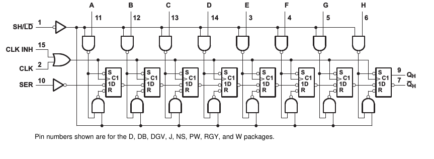
shift register SN74LV165

The picture is from the Texas Instruments SN74LV165A datasheet.

The idea is the following: When the SH pin is pulled low, the values at pins A-H are stored in the internal flipflops, so this is where you connect your switches/buttons that either connect the pin directly to supply voltage (if pressed, for example), or ground the pin throug a (largish) resistor:

schematic

simulate this circuit – Schematic created using CircuitLab

That way, when the button is pressed, the voltage at the input is "high", otherwise it's low. It's usually recommendable to connect a capacitor in parallel to the resistor, because that will counter so-called "bouncing". The actual resistor and capacitor values aren't critical – if you use a resistor value that's too small, you'll draw a lot of current with every button pressed, and if you choose a capacitor value too large, buttons will appear to take a long time until they are effectively pressed and released, but in general, something like 10kOhm and 10nF – 100nF, values abundant in most part boxes, should do well for human interaction.

Yet another hint: if you need to go shopping for parts, buy so-called resistor networks; for example, there's parts that contain 8 identical resistors that have one common pin (which you'd connect to ground here, and 8 individual pins. That way, you save yourself a lot of soldering work, and your circuit can look very clean and tidy.

Now, having pulled SH "high" again, the input values are stored in the flipflops.

Now your microcontroller would start to send a clock signal (high,low,high,low,…) to the CLK input. At every rising edge (i.e. low-to-high transition), an input value appears at QH, and the internal states are pushed one step "to the right", meaning that the second flipflop then contains the old value of the first, the third flipflop the old value of the second and so on. After six clock cycles, all the 8 input values have been sequentially shown on QH. That's why this shift register is usually also called a parallel to serial converting shift register.

You can actually daisy-chain those: if you take a second shift register and attach its QH to your shift register SER input, then the output values will be "concatenated" to your first shift registers values. That way, with only three pins on your Arduino (one pin driving SH, one pin driving CLK, and one pin reading the serial output from QH), you can have virtually unlimited amounts of buttons – and that at a unit price of less than 20ct per 8 inputs

The only limiting part is that you regularly have to pull down SH, pull it back up, and generate 8*(N_shiftregisters) clock cycles; this has to be done often enough not to miss a key press – but usually, with microcontrollers running at MHz's, and with SPI hardware that actually is meant for nothing different than talking to such shift registers, this isn't a problem at all – it's not uncommon to see someone query shift registers a couple thousand times per second.

\$\endgroup\$
3
  • \$\begingroup\$ capacitors like that cause increased switch wear. if you must do analogue debounce use positive feedback. else do software debounce. \$\endgroup\$ Commented Jul 24, 2016 at 11:35
  • \$\begingroup\$ @Jasen Haven't heard of that argument – you mean because of the high charge current flowing through the switch when pressed? Yes, in theory, there should be a resistor between the switch and the capacitor, but in practice, you can often do well enough by designing your traces thin enough to not let the current go through the roof. Or you assume that keypad switches are robust enough and they'd be attached with non-superconductive cabling, anyway (I'd be more worried about parasitic inductance leading to voltage spikes here, to be honest, than about the current flowing). \$\endgroup\$ Commented Jul 24, 2016 at 11:52
  • \$\begingroup\$ @Jasen hope my edited circuit explains that well enough. \$\endgroup\$ Commented Jul 24, 2016 at 11:57
2
\$\begingroup\$

If you have 3 I/O pins, you could charlieplex them.

Charlieplexing

(You should add a pull down resistor before each I/O pin.)

Image source: http://www.pcbheaven.com/wikipages/images/charlieplexing_1302615143.jpg

Now as a note, you have to test all the possible combinations (6 in total) before determining which buttons are pressed and which ones are not. If you activity one pair of pins and find that there is continuity, there are three possibilities, where current could flow through two pressed down buttons (kinda in series), one pressed down button or all 3.

This is what I mean: enter image description here

Also, ensure you DO NOT set any OUTPUT to LOW. If you want to prevent something from burning, put like a 1kΩ resistor at each terminal. But that would unintentionally create a voltage divider.

\$\endgroup\$
4
  • \$\begingroup\$ I think you need to have pull-downs on the inputs to not have floating inputs when none of the buttons are pressed. ATmega has internal pull-ups, though, so you could invert the logic and enable pull-ups on all but one pin at a time, and drive that one pin low. (Without using external pull-up/pull-down resistors) \$\endgroup\$
    – ilkkachu
    Commented Jul 23, 2016 at 12:17
  • \$\begingroup\$ @ilkkachu Oh wow thanks for telling me that I will edit the question. \$\endgroup\$
    – Bradman175
    Commented Jul 23, 2016 at 12:29
  • \$\begingroup\$ I'm going to ask a silly question. Will the internal PULLUP accidentally power the circuit? \$\endgroup\$
    – Bradman175
    Commented Jul 23, 2016 at 12:38
  • \$\begingroup\$ the pull-ups should pull the pins high, except for the one actively driven low or the ones connected to the low pin via the switches and diodes. There isn't really anything to be powered in that circuit, and the pull-up is weak anyway. You'd just need to interpret a high value the default and a low value the signal for a button press. (And also consider that the current through the diodes would be inverted too.) Other than that, I don't think it should matter if you have a pull-up or a pull-down. \$\endgroup\$
    – ilkkachu
    Commented Jul 23, 2016 at 12:58
2
\$\begingroup\$

You state parameters of:

  • At least six switches
  • At least two controllers
  • Arduino Nano-compatible
  • Using as few I/O pins as possible

Using a digital interface instead of an analog one will give you improved noise tolerance and eliminate accuracy requirements of DAC resistors.

If you search for "I2C keypad controller", you will get several possibilities.

Features of a keypad controller which you might want to take into consideration when selecting a part are inbuilt key debouncing (makes your software/hardware a bit simpler), ESD protection (the user could be a cat), and a user-definable address (so you can have more than one on the same I/O pins).

One of them is the MAX7360 Keypad Controller (this is not a product recommendation as I have no experience with it, and EE.SE is not a product recommendation site).

If you find that your selected device prefers to work with a 3.3 V I²C bus but your Nano works with 5 V, you can use a level-shifter.

Another point to consider is if you can physically solder the device - some of the ones I found use a BGA package. If you have a hot-air soldering station then that will be usable for you, otherwise go for one with pins at the edges.

\$\endgroup\$
2
  • \$\begingroup\$ By far the lowest effort and most likely to be done perfect approach! \$\endgroup\$ Commented Jul 24, 2016 at 19:19
  • \$\begingroup\$ @MarcusMüller I feel like it's having a programming language with a ready-made "SpaceInvaders" instruction :-| (Previous comments of mine removed.) \$\endgroup\$ Commented Jul 24, 2016 at 19:27

Your Answer

By clicking “Post Your Answer”, you agree to our terms of service and acknowledge you have read our privacy policy.

Not the answer you're looking for? Browse other questions tagged or ask your own question.