I'm building a small battery powered temperature sensor gadget thing. I've bread-boarded the circuit and it worked great. I then proceeded to create small PCB out of it.
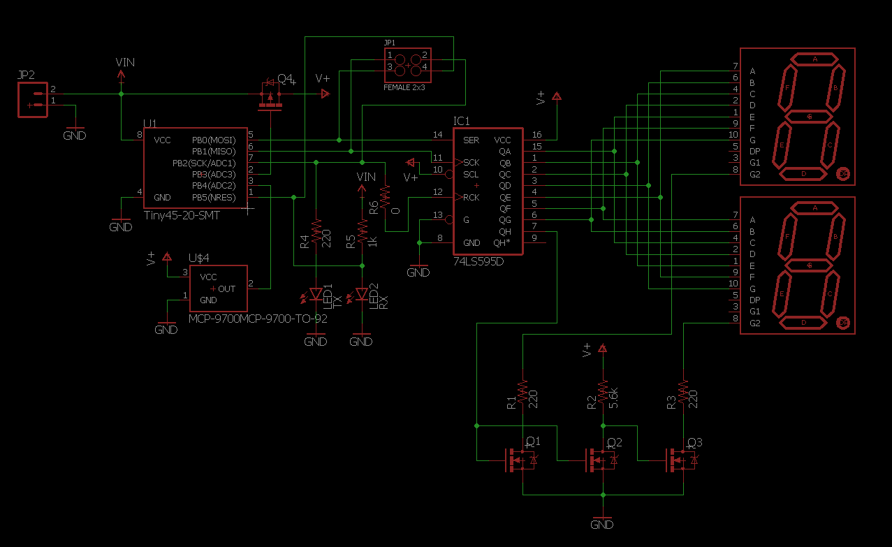
I've attached the schematic below but the basic idea was to power an attiny85 from a CR2032 coin cell and display the temperature on two 7 segment displays. The temperature is measured using the attiny85s internal 1.1V reference and is connected to ADC2.
The temperature sensor I'm using is the MCP 9700 from Microchip. It has a 10mV/degC temperature coefficient with a 500mV output corresponding to 0 degrees C. It has an accuracy of +- 4 degC which corresponds to a voltage of 40mV.
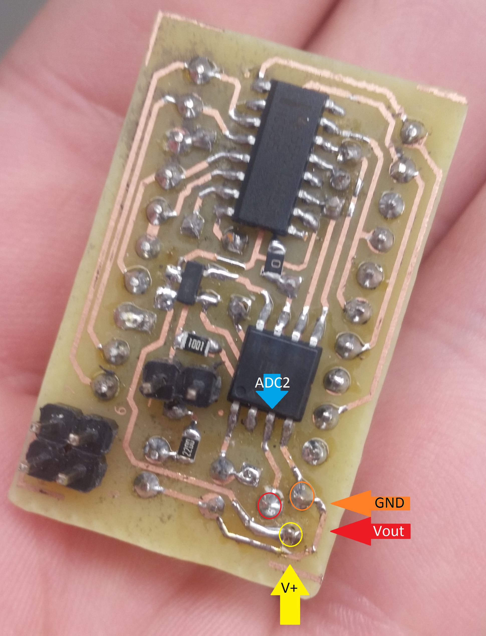
After testing all other components on the PCB and flashing the attiny85, I then soldered the MCP 9700 to the board. When I applied power, the reading was around 45 degrees C so I figured it must just be residual heat from the soldering process. I left the board un-powered for about an hour. When I switched it on again, the temperature was reading between 10 and 15 degrees too high still. I thought maybe the MCP 9700 I soldered on was dodgy, so I desoldered it and soldered on a new one. I let it cool down over night and it has the same issue.
I also noticed that when varying the supply voltage from 5V down to 3V, the output of the temperature sensor varies by as much as 10 degrees C or 100mV. The MCP 9700 is meant to be quite constant over supply voltage. The same temperature sensors on the breadboard do not exhibit this behavior.
I got the components from Digikey so I don't think they're fake or anything like that. Also, the same temperature sensors work perfect on the breadboard. The code on the attiny85 is correct. I've confirmed this by checking the raw ADC value against the output voltage of the temperature sensor using a Fluke 87V. This leads me to believe that it must be some type of construction issue. I've checked each trace over and over again, confirmed there are no shorts and that the circuit is correct.
I have been banging my head trying figure out why this is. Any ideas on what could be wrong?


