1
\$\begingroup\$

Let's say I have this design for example:

library ieee;
use ieee.std_logic_1164.all;

entity adder is
port(x : in std_logic_vector(3 downto 0);
     y : in std_logic_vector(3 downto 0);
     z : out std_logic_vector(4 downto 0));
end entity adder;

architecture rtl of adder is
    signal c : std_logic_vector(3 downto 0);
begin
    adder_gen : for i in 0 to 4 generate
        half_adder_gen : if i = 0 generate
            z(i) <= x(i) xor y(i);
         c(i) <= (x(i) and y(i));
   end generate half_adder_gen;
        full_adder_gen : if 0 < i and i < 4 generate
            z(i) <= x(i) xor y(i) xor c(i-1);
         c(i) <= (x(i) and y(i)) or ((x(i) or y(i)) and c(i-1));
        end generate full_adder_gen;
        overflow_gen : if i = 4 generate
            z(i) <= c(i-1);
        end generate overflow_gen;
    end generate; 
end architecture rtl;

Usually if I run a design like this what I see in the waveform is that ALL the bits of the output changes instantaneously as soon as the input bits change as well. However this behaviour is not what I expect in this case, I would expect that the output bits y(4) ... y(0) changes when the value of c(i) is known, but such bit depends on the c(i-1) and so on... Is there something I'm miss understanding?

\$\endgroup\$
1
  • 1
    \$\begingroup\$ For a suitable definition of "instantaneous". Track individual delta cycles to see what's really going on. While the gate level simulation answer is correct, in practice you rarely to never need gate level sims - at least in synchronous designs in FPGA, \$\endgroup\$
    – user16324
    Commented Aug 2, 2016 at 10:23

1 Answer 1

1
\$\begingroup\$

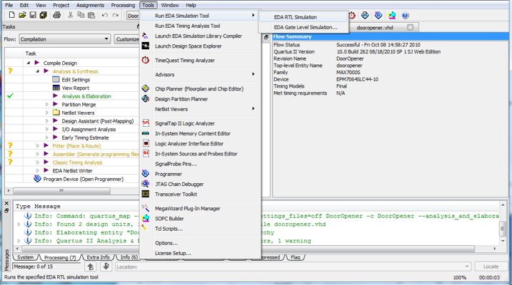
This is what you would expect, if you run the, so called, RTL simulation. Your tool chain should have a gate level simulation, which takes the synthesized design for your target device, and gives the simulator the specific delays. This is where they are in Quartus: simulation

\$\endgroup\$
9
  • \$\begingroup\$ Ok, maybe I got it. The RTL is the logic simulation, while the gate level exploits the physical features of the gates specified in the netlist, am I right? \$\endgroup\$ Commented Aug 2, 2016 at 10:29
  • 1
    \$\begingroup\$ Yes. However, it is not the netlist, but rather the synthesized design. Also, RTL simulation is faster. I usually do RTL -> timing closure. The gate level is useful, if you want to pipeline something. You can see what the delays are for each section \$\endgroup\$
    – user110971
    Commented Aug 2, 2016 at 10:33
  • \$\begingroup\$ Isn't the output of the synthesis the netlist? \$\endgroup\$ Commented Aug 2, 2016 at 10:40
  • 1
    \$\begingroup\$ The netlist is like a circuit diagram of the gates. The synthesized design actually places the gates and gives you the interconnect delays. \$\endgroup\$
    – user110971
    Commented Aug 2, 2016 at 10:43
  • \$\begingroup\$ I thought the netlist was a kind of graph where each node has physical properties, like resistance, capacitance, delay of propagation, from that I supposed it was possible to retrieve the info about the whole propagation. \$\endgroup\$ Commented Aug 2, 2016 at 10:53

Your Answer

By clicking “Post Your Answer”, you agree to our terms of service and acknowledge you have read our privacy policy.

Not the answer you're looking for? Browse other questions tagged or ask your own question.