Any design that requires the exact value of the \$h_{FE}\$ of a BJT is a faulty design, since that parameter is subject to wild production spread.
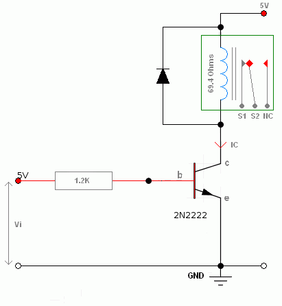
Since in your case you only need the \$h_{FE}\$ to calculate the base current required to turn the BJT on, assume the worst possible case reported in the datasheet.
In this case worst possible case means lowest possible value of \$h_{FE}\$ in your working conditions. For any small signal BJT assuming \$h_{FE}\$ to be at least 10 (for the purpose of turning it on) is almost sure-fire. In other words, use a base current that is ten times smaller than the maximum collector current you need to drive and you'll be safe.
If the current you must provide to the base turns out to be too big for your driver circuit, you can use a Darlington transistor (or another BJT connected as a Darlington pair). In which case the minimum \$h_{FE}\$ (without even looking at the datasheet) can be assumed as 100 (VERY conservative estimate for a Darlington BJT, it's likely higher; it is OK for two 2N2222 connected as a Darlington pair).
If you want to be more fussy, the \$h_{FE}\$ depends essentially on both \$I_C\$ and temperature. If you want a tighter estimate take the lowest value you find in the datasheet, as you can see in an excerpt of a Fairchild PN2222 datasheet, a more modern and cheaper equivalent of the now obsolete 2N2222 (yellow emphasis mine):

In this case it is generally safe to assume a min \$h_{FE}\$ value of 35.
EDIT (prompted by a comment)
Computing the \$h_{FE}\$ when the BJT is saturated is not meaningful. \$h_{FE}\$ is a parameter which has some meaning when the BJT operates as a linear device, i.e. as an amplifier. When you turn the BJT on you are actually overdriving the BJT out of its linear region (a.k.a. active region).
When you perform your calculations to determine how to bias the BJT to get the level of overdrive needed to turn it on, you are simply using \$h_{FE}\$ as a gross indicator of where the device will stop behaving linearly. In other words you drive it with a base current that cannot be amplified linearly by the device, so it is forced into saturation (i.e. it is turned on).
To be more explicit, let's say that the min \$h_{FE}\$ is 10. This means that if the device is driven with 1mA Ib it will have a 10mA Ic if the output circuit allows it. If, for a given level of Ic, say 10mA, you drive the base with much more than Ic/10=1mA, you are forcing the BJT out of the linear region (where "there is no \$h_{FE}\$").
EDIT
Sometimes even on technical literature there is some ambiguities as what \$h_{FE}\$ is. Technically \$h_{FE}\$ is defined as:
$$
h_{FE} = \frac{I_C}{I_B}
$$
It is sometimes conflated with the β found in the Ebers-Moll model, but that is only an approximation valid in the active region. Out of the active region you can still measure \$h_{FE}\$, but it will no longer be approximately equal to β. In this case some texts talk about a parameter called βforced which is always less than β in the same conditions (bar a different Ib).
The point here is that \$h_{FE}\$ is a somewhat useful parameter only in the linear region because it is fairly constant (if the temperature is held constant and Ic doesn't vary too much) and it expresses the (approximately) linear relationship between Ib and Ic that is valid in the linear region.
This is also related to the similarly meaning \$h_{fe}\$ small-signal parameter (note the lowercase subscript). Which is defined as:
$$
h_{fe} = \frac{\partial I_C}{\partial I_B}
$$
that is it is the slope of the curve \$I_C=I_C(I_B,V_{CE})\$ when holding \$V_{CE}\$ constant. In the linear region that curve is well approximated by a straight line, hence \$h_{fe}\approx h_{FE} \approx \beta\$.


