4
\$\begingroup\$

INPUT: I start with a variable DC supply (rated up to 5A) that varies between 0V and 24V.

OUTPUT: Let's say I'd like to get a directly proportional output voltage between 0V and 5V (i.e. a re-map of the original range, so that 0V becomes 0V, and 12V becomes 2.5V, and 24V becomes 5V, etc.).

CURRENT DRAW AT OUTPUT: Assume this final output voltage (which varies between 0 to 5V) will be used to power a motor that draws a maximum current of approximately 1A. So, the motor's speed would change as the original supply, and thus the reduced supply, changes.

Is it possible to do the above? Regulators are out for obvious reasons, and a voltage divider would create a lot of heat and doesn't sound like the ideal solution.

EDIT:

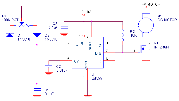
A few people suggested PWM would be a simple solution, so I researched a bit and found this example of achieving PWM with a 555 timer (further questions below):

circuit

Is this a suitable implementation for my purpose, or is there a ready-to-use PWM-performing IC that I can try applying within my circuit?

Additionally, I looked up LM555's datasheet, and it seems to operate at max. supply of 18V, whereas I need up to 24V. Any suggestions on this front?

\$\endgroup\$
10
  • \$\begingroup\$ "Regulators are out for obvious reasons" Why? Because the current draw would appear to be too high? That's why switching regulators and MOSFETs are used for this. \$\endgroup\$ Commented Aug 8, 2016 at 13:03
  • \$\begingroup\$ I meant because a regulator (at least typically?) would output a fixed voltage, as opposed to something continuously proportional to the varying input voltage. \$\endgroup\$
    – boardbite
    Commented Aug 8, 2016 at 13:05
  • 3
    \$\begingroup\$ ... Use a voltage divider for the reference voltage. You may not be able to use a COTS regulator, but it can definitely be done. \$\endgroup\$ Commented Aug 8, 2016 at 13:06
  • 2
    \$\begingroup\$ Sounds like you want PWM with a fixed duty cycle of 5/24. \$\endgroup\$
    – user16324
    Commented Aug 8, 2016 at 13:11
  • 1
    \$\begingroup\$ @BrianDrummond Keep in mind that that requires continuous conduction mode. As long as you have that in all load conditions, fixed PWM is the fast and easy solution. \$\endgroup\$
    – winny
    Commented Aug 8, 2016 at 15:38

2 Answers 2

2
\$\begingroup\$

An open-loop buck converter could be used, preferably with synchronous rectification.

The switches should operate with a 21% duty cycle, which will give you about 0-5V. There will be some droop with increasing current, due to the inductor resistance (typically a large contributor) and Rds(on) of the two MOSFETs.


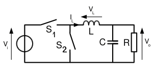
Edit: Conceptual diagram:-

enter image description here

S1 and S2 can be MOSFETs or S2 could be a Schottky diode. S1 closes with duty cycle D and S2 closes for D' = 1-D where D ~= 0.21 . The period Ts is kept short enough that there is only maybe 15% current ripple in L and C is chosen to keep the output ripple voltage within requirements.

For example, if the frequency is 100kHz then Ts = 10usec and S1 would close for 2.1usec and then open, and S2 would close for 7.9usec and open, and repeat forever.

Note that if S1 and S2 are closed at the same time, even for a relatively short time, bad things will happen as they would be shorting the supply out.


To get better accuracy would require a closed-loop control circuit- measuring the '24V' supply and servoing the output to a fixed fraction of it. That would be a bit more complex.

\$\endgroup\$
6
  • \$\begingroup\$ I am OK with small losses/inacuracy in the conversion. Can you expand on how an open-loop buck converter would be achieved? Or do you mean an off-the-shelf buck converter would be used in a non-standard way? \$\endgroup\$
    – boardbite
    Commented Aug 8, 2016 at 13:17
  • \$\begingroup\$ I added a conceptual diagram above. \$\endgroup\$ Commented Aug 8, 2016 at 14:16
  • \$\begingroup\$ I don't think this is a good solution for a motor. As voltage goes down the torque goes down abruptly \$\endgroup\$ Commented Aug 8, 2016 at 16:29
  • \$\begingroup\$ @ClaudioAviChami The circuit as shown above can have very low output impedance which (along with the motor resistance) determines the available torque. The speed of a brushed DC motor will decrease proportional to voltage but torque will not fall off that rapidly, certainly nothing like adding a resistance in series because this is a 'stiff' supply. One step up from this is to have slightly negative output impedance to compensate for the motor resistance. \$\endgroup\$ Commented Aug 8, 2016 at 16:40
  • 1
    \$\begingroup\$ @ClaudioAviChami Most of the source voltage goes to cancel the back EMF- that's why the LRA is so much higher than the run current on a typical brushed DC motor. Actually 1/3 duty cycle PWM and 1/3 voltage are exactly the same thing if the motor inductance is high enough to avoid excessive ripple (and if it isn't the motor and MOSFETs will get very hot because of huge RMS current and magnetic losses. Try putting a DC motor on an adjustable regulated (eg. bench) power supply and you will see. \$\endgroup\$ Commented Aug 8, 2016 at 21:12
1
\$\begingroup\$

For what you want to do there is a far better approach than reducing the voltage. It is to use PWM from the Vcc to the motor. Reducing the voltage is bad because of the losses if you use linear regulation... but even if you use a switching power supply, reducing the voltage is bad because of the torque loss.

The PWM is a switching solution (no losses) with almost no loss of torque.

\$\endgroup\$
2
  • \$\begingroup\$ I am a bit new to PWM implementation in hardware (aside from writing code to use PWM-capable pins on a microcontroller). Could you add a bit more detail on how PWM would be achieved in this situation (i.e., custom-set duty cycle)? Are you talking about using an off-the-shelf part, or a transistor-based circuit which is dynamically controlled by a microcontroller? \$\endgroup\$
    – boardbite
    Commented Aug 9, 2016 at 1:31
  • \$\begingroup\$ I have added an EDIT to my question text, based on some initial study of PWM. If you could answer the doubts I brought up in the edit, that would be appreciated. \$\endgroup\$
    – boardbite
    Commented Aug 9, 2016 at 1:52

Your Answer

By clicking “Post Your Answer”, you agree to our terms of service and acknowledge you have read our privacy policy.

Not the answer you're looking for? Browse other questions tagged or ask your own question.