I was tempted to just add additional notes, now that you've later specified that you need \$I_{pk}=1A\$ for your LED. But it seems better to just revise everything on the basis of the new information and ditch the extraneous bits and questions I'd asked earlier and just get to the point.
(Your use of a PNP, especially because you are coming from a 0-5V I/O pin and connecting the PNP BJT directly to +12, is fraught with issues some of which I guess you encountered.)
So, let's re-state the requirements, discuss my worries a little, and lay out a schematic to follow for your PWM circuit.
First off, I'm going to assume that you do not need any current-limiting. If you supply a voltage source that is capable of delivering nearly \$12V\$ to the LED, then it should just work right. No need of a circuit to help it, then.
Second, I'm going to assume that you have a \$12V\$ power supply rail that is rated for your use. If you say you need \$1A\$, I'll assume your power supply can handle that without difficulties and still achieve the rated \$12V\$ output voltage.
Third, I'm going to assume that \$1A\$ is your maximum current required and that you expect to dim things down from there using PWM. Not that you need some other peak current, where say \$50\%\$ duty cycle is the equivalent of \$1A\$ brightness.
Fourth, just to be very safe about it and to allow room for other I/O pins to also deliver current where needed, I'm going to assume that you only should expect a maximum sink/source of \$3mA\$ from your output pin. Keep in mind that your micro has lots of I/O pins and that some of these I/O structures are close together on the die. If you start using lots of I/O for different things and make larger assumptions based on the idea that the specifications tell you the max that one I/O can handle, then you could get into trouble just the same because you didn't take limitations of the entire cpu, or specific ports of the cpu, into account. (Less is better, of course. And I'm pretty sure it can handle about three times that.) So I'm going to stick hard to that number. You can make other choices.
BJTs that are rated to handle \$1A\$ are usually found in TO-220 or TO-3 packaging. However, even the lowly 2N2222A is rated at a continuous \$600mA\$ (in unusual circumstances and lower \$\beta\$ because of current crowding, anyway.) But in general, this is just enough over the wire that you should not waste a lot of time looking for some small signal packaging. This applies to MOSFETs, too. So let's take it as a given that you will use either a TO-220 or TO-3 package for your driver transistor. Once you have made that decision, the cost difference between BJT and MOSFET starts to disappear. So either choice is probably a good one. In my case, I'm going to stay with a BJT. Others will offer some good MOSFET choices. To each their own.
Let's get to the schematic:

simulate this circuit – Schematic created using CircuitLab
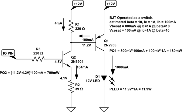
I actually used datasheets to make sure I was providing a situation that would work, regardless of reasonable variations in parts. The required current loading on your I/O pin will likely be \$500\mu A\$, but should in almost all cases be less than \$1mA\$. This is even better than I'd hoped, earlier.
One concern is about speed. But it should work even if you fed it a \$100kHz\$ square wave at \$50\%\$ duty cycle. So I think it will be okay. You could remove \$R_3\$, since the I/O probably already has about \$100\Omega\$ output impedance to it. \$R_3\$ is mostly there about oscillation worries, where I'm not all that worried. But adding one right away makes it easier to change.
I've added some power calculations there. I'm mostly worried here about \$Q_2\$, which looks like about \$700mW\$ when turned on and active. That's fine if you can get a BJT for that position which can dissipate that much into the air. However, you could distribute most of that wattage into a resistor, instead. The new schematic would look like:

simulate this circuit
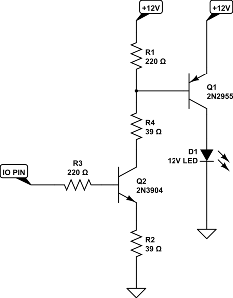
I chose another \$R_4=39\Omega\$ resistor to add into the circuit because maybe it is easier to get two of them rated for at least \$1W\$ than to get two different values. The value could be made larger, so perhaps \$R_4=47\Omega\$ would be good. But even as it is shown, \$Q_2\$ now only dissipates about \$\frac{1}{4}W\$. And this is probably very doable with most devices in most circumstances. But if you used \$R_4=47\Omega\$, \$Q_2\$'s dissipation then drops to about \$150mW\$.
The purpose for \$R_4\$ is to pick up some of the needed voltage drop so that the collector of \$Q_2\$ doesn't have to reach up so high. This transfers dissipation from \$Q_2\$ to \$R_4\$. It doesn't really matter where the voltage drop takes place, so this is a harmless way to move dissipation away from the BJT. It otherwise doesn't really affect the circuit's function.
That said, do also keep in mind that you need resistors that can dissipate some heat for \$R_2\$ (and \$R_4\$, if used.) Should be rated at least \$1W\$. (\$R_1\$ and \$R_3\$ dissipate too little to worry about.)
HUMAN VISION NOTES:
Now for some news. The following is my own writing, but drawn from some experiences.
The Talbot-Plateau law in the field of visual perception states that if a light source blinks fast enough that it passes beyond the critical flicker fusion frequency (CFF), then the brightness will appear to be the same "as if" the light source were steadily operated at the time-averaged luminance. In other words, if you operate the light source at twice the luminance but only half the time (50% on and 50% off, flickering faster than the CFF), then it will appear to have the same luminance as that similar light source operated at the lower luminance.
This Talbot-Plateau law reflects on your PWM frequency choice. Make it fast enough to eliminate the appearance of flicker.
Keep in mind that operating a light at a 50% duty cycle, above the CFF, does not mean that it will appear half as bright as one operated 100% of the time. It means that operating a light at 50% duty cycle (and faster than the CFF) will make it appear the same brightness as another operating at half the luminance. There is a difference in meaning.
The reason it doesn't look "half as bright" when operating at a 50% duty cycle is that the human eye works according to another law, the Weber-Fechner law. That one states that intensity goes as the logarithm of the physical stimuli.
Well, almost. There's a pair of other ones, the Broca-Sulzer effect and the Bruecke-Bartley effect, that operate at flicker frequencies below the CFF. At around 50ms on-duration and 50ms off-duration, for example, a blinking light source will appear to be brighter than the time-averaged luminance ... in apparent violation of the Talbot-Plateau law. But the Talbot-Plateau law doesn't apply at such low frequencies, so it isn't really a violation.
Actually, there are a lot of "laws" in the field of visual optics and optometry. These are just three or so out of many more.
Varying the LED intensity smoothly as the human eye perceives it isn't as simple as linearly varying the PWM duty cycle. Our eyes have a roughly logarithmic response (Weber-Fechner law, already mentioned.) This is a biological necessity. We need to use our eyes in broad daylight, at high noon, on the equator. And we still need to use them on a dark, moonless night. To cope with all this, our eyes have evolved responses that vary in more of a logarithmic fashion. (As the Weber-Fechner law states.)
When we ask ourselves to "adjust the brightness, linearly" this should roughly (1st order estimate) mean we need to vary the current in an LED exponentially. (Our eyes will take the logarithm of that and that will flatten the resulting 'curve.') This means we need to take a different approach than just trying to vary the current (or PWM duty cycle) in a linear way, or else just give up on that idea and do what "comes easy."
This means that the duty cycle in a PWM needs be adjusted on a percent by percent basis (geometrically, in effect) in order to approxiate an exponential. That way, our eyes will perceive a linear change in the LED output.
Bottom line? If all you do is linearly adjust the PWM duty cycle by fixed increments, then you won't really get something that looks smooth to the eye.
Just thought I'd toss that in to complicate your life.
(And then I'm going to discuss something that may push your understanding a bit more and hasn't been covered here, either.)


