0
\$\begingroup\$

I am making a device based on a STM32F105 (3v3) that has to accept inputs that I am not in control of, for example in a vehicle or other wiring that I cannot change.

The device is to have 16 inputs.

I want the input to be selectable between active low and active high. Because sometimes I might come across a switch that is switched to GND and sometimes one that is switched to say 30v.

All inputs have to be 30v tolerant.

I would like to have the option of selecting in firmware whether the input is connected to a switched Ground or switched positive.

How can I go about accepting inputs that could be switched GND or on other occasions be switched 24v?

For example I may come across either of the following so I need my circuit to be able to accept both:

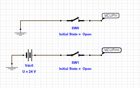
enter image description here

\$\endgroup\$
4
  • \$\begingroup\$ What is the device based on? \$\endgroup\$
    – HandyHowie
    Commented Sep 1, 2016 at 12:49
  • \$\begingroup\$ 30 V tolerant is easy, use an input series resistor and a zenerdiode to clamp the voltage down to the level which the next circuit needs (like 5 V). For the rest it is not so clear what you want, maybe you should provide an example in the form of a schematic. \$\endgroup\$ Commented Sep 1, 2016 at 12:58
  • \$\begingroup\$ Your question in the title is different from the question at the end. As to the question at the end, one way to selectively invert a signal is to use an exclusive-or gate. \$\endgroup\$
    – rioraxe
    Commented Sep 1, 2016 at 21:18
  • \$\begingroup\$ STM32F105 already have "software selectable Pull Up & Pull Down Inputs". Read the GPIO section of reference manual carefully. After you make it input mode, you choose either it is floating or pulled. Pulling direction is dictated by output register. \$\endgroup\$
    – Ayhan
    Commented Sep 2, 2016 at 13:25

2 Answers 2

1
\$\begingroup\$

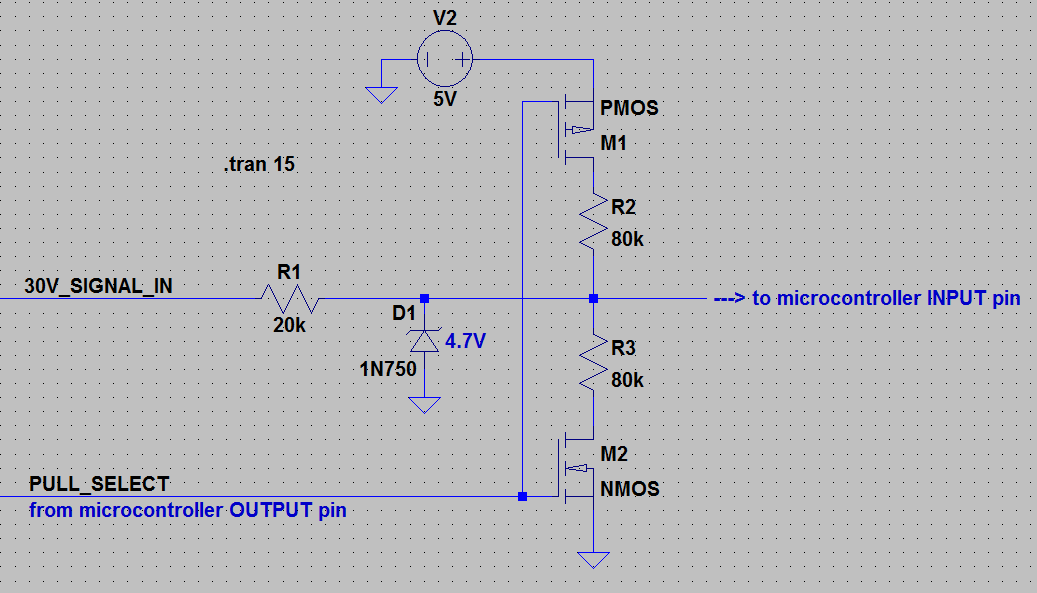
How about:

This assumes a 5V microcontroller, common ground between 5V and 30V circuits and suitably chosen mosfets.

Note that M1 (P-Channel mosfet) is installed with the source facing the 5V rail.

When your microcontroller outputs a logic high, the N-Channel turns on and the P-Channel turns off (simultaneously) which enable the pull-down R3. A logic low will do the opposite and turn on the pull-up R2. D1 and R1 are the protection circuitry to drop the 30V level down to something the micro will be happy with.

Additional info: This circuit can be modified slightly to put the pull-up/down on the high-voltage side if you want that instead, just move D1 & R1 to be on the microcontroller side and use mosfets suitable for 30V switching.


\$\endgroup\$
8
  • \$\begingroup\$ Ok that looks like what I need. My microcontroller is a 3.3v STM32F105. So I guess all I would need to do is to changed the Zener and possibly R1. How would I go about choosing the correct Mosfets? \$\endgroup\$ Commented Sep 1, 2016 at 16:11
  • \$\begingroup\$ For programmable pull-up/down there's no need for MOS or anything else, you just need one resistor. Say you only have R2 in schematics above, you wire it directly to one uP output pin, the you can program it high or low for pullup/pulldown or even hi-z for no-pullup \$\endgroup\$
    – carloc
    Commented Sep 1, 2016 at 19:30
  • \$\begingroup\$ @TerryGould, the switching threshold wants to be somewhere around +/-1.65v and the Vds wants to be above 3.3v so it can accommodate your microcontroller. Farnell, Digikey or Mouser have good part selection filters on their websites. \$\endgroup\$
    – user98663
    Commented Sep 2, 2016 at 6:46
  • \$\begingroup\$ @carloc, put that in the form of an answer and I'll upvote it. \$\endgroup\$
    – user98663
    Commented Sep 2, 2016 at 6:47
  • \$\begingroup\$ What are the benefits of using this approach to just using @carloc 's solution or using the configurable pull resistors in the mcu? Would this offer any more protection to the MCU pin or other components? \$\endgroup\$ Commented Sep 2, 2016 at 14:26
0
\$\begingroup\$

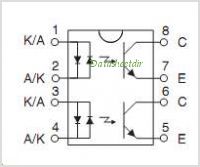
enter image description here

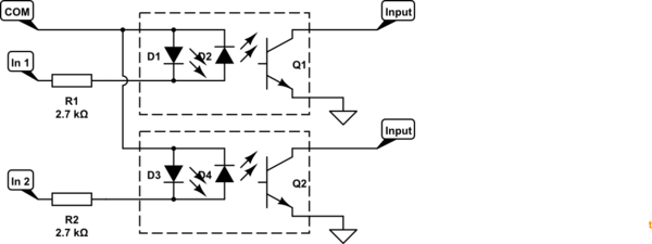
Figure 1. Opto-isolators such as the LDA202 are bidirectional which eases terminal configuration.

schematic

simulate this circuit – Schematic created using CircuitLab

Figure 2. Typical common + or common - input configuration for PLCs.

This arrangement has several advantages:

  • Full opto-isolation of micro from the external power sources.
  • If the opto-isolators are socketed then repair is simple.
  • The inputs can have a common ground or common 24 V. Group optos together to allow flexibile connection of both types of input by the user.

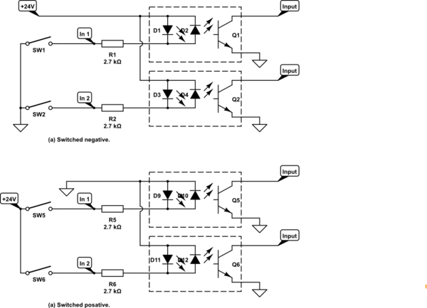
schematic

simulate this circuit

Figure 2. Wiring arrangements for switched negative and switched positive connection.

\$\endgroup\$
5
  • \$\begingroup\$ So I connect IN1 to Ground and IN2 to VIN say 24V, I would still need some extra circuitry to make the input 24V tolerant. The only down side I can see is having two output pins for the pull-select. \$\endgroup\$ Commented Oct 4, 2016 at 9:35
  • \$\begingroup\$ I don't think you've got it yet. That one chip gives you to opto-isolated inputs. (1) If your switches connect to GND then connect COM to +24V and connect the two switches to In1 and In2. (2) If your switches connect to +24V then connect COM to GND (24V-). (3) You can apply 24 V directly between COM and either input as shown. The 2k7 resistor will limit current through the opto-LED to about 8.5 mA and power dissipated in the resistor will be about 0.2 W. No extra circuitry required. \$\endgroup\$
    – Transistor
    Commented Oct 4, 2016 at 9:49
  • \$\begingroup\$ Yep I understand now! What if wanted to select ground or 24v for every input how could I do this through firmware? \$\endgroup\$ Commented Oct 4, 2016 at 12:26
  • \$\begingroup\$ You can't. That selection is done on the hardware simply by the wiring. The way I've shown the opto-isolator transistors is that they pull to ground when the LED turns on whether switched positive or switched negative. The micro will never see the 24 V circuit and can't configure it. They're completely opto-isolated. Don't forget to use the internal pull-ups in the micro. \$\endgroup\$
    – Transistor
    Commented Oct 4, 2016 at 13:02
  • \$\begingroup\$ See Figure 2 for clarification on connection options. \$\endgroup\$
    – Transistor
    Commented Oct 4, 2016 at 13:44

Your Answer

By clicking “Post Your Answer”, you agree to our terms of service and acknowledge you have read our privacy policy.

Not the answer you're looking for? Browse other questions tagged or ask your own question.