0
\$\begingroup\$

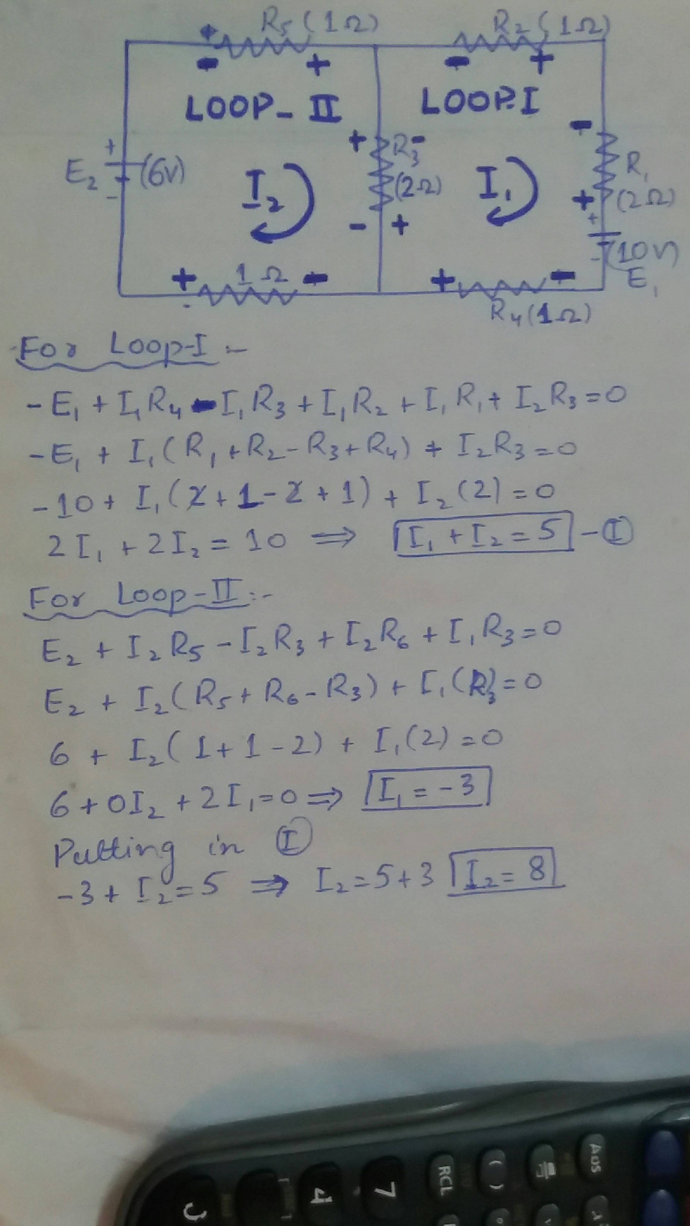
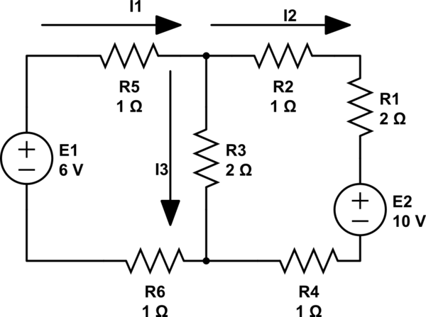
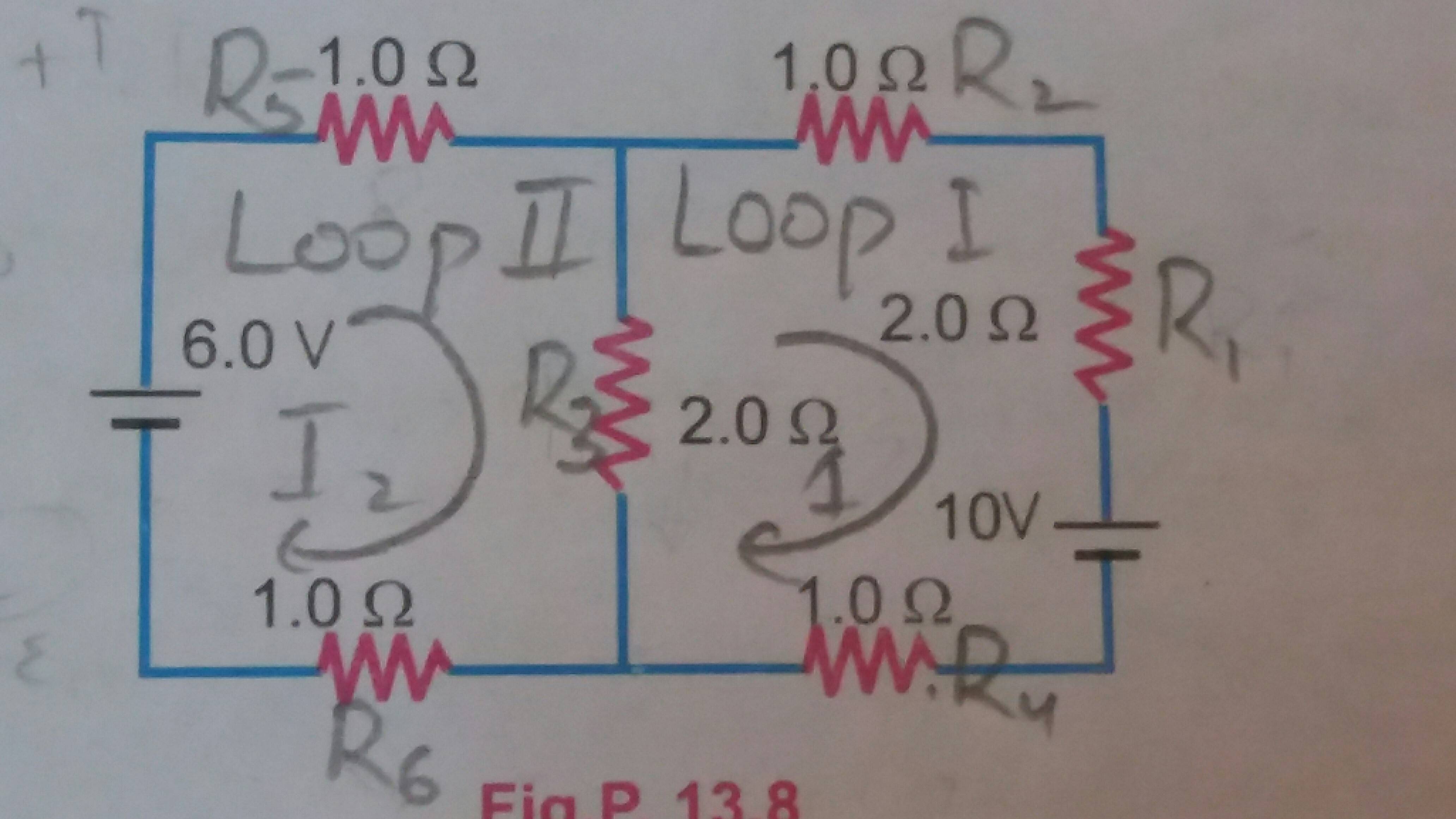
I have to compute current in the resistors shown in the following diagram Which I have done as follows:

Which I have done using mesh analysis as follows:

enter image description here

However the correct values of currents passing through the resistors are given to be 0.8 , 1.4 , and 2.2 amperes. Where have I done mistake in the whole method?

\$\endgroup\$
2
  • \$\begingroup\$ To eliminate the error when writing mesh equations you should always be consistent with your sing convention. And remember that the polarity of the resistor depends on the direction of the loop current going through that resistor. If loop current enters the resistor you always should give it a "+" or "-" sign. For exampel in loop II we have E2 and the loop current enters E2 from the "-" side so let us give it a "-" as for the resistors we give a "+" if the loop current enters the resistor. -E2 +I2*R5 + (I2 - I1)*R3 + I2*R6 = 0 \$\endgroup\$
    – G36
    Commented Sep 4, 2016 at 14:35
  • \$\begingroup\$ If we use the same convention for loop; I we have E1 + I1*R4+(I1-I2)*R3+I1*R2+I1*R1=0 and the current trough R3 is equal to IR3 = I2 - I1. And this time we have E1 because loop current enters E1 form "+" side. \$\endgroup\$
    – G36
    Commented Sep 4, 2016 at 14:36

5 Answers 5

0
\$\begingroup\$

In loop 1 we have R1,R2,R3 and R4.

In loop 2 we have R5,R6,R3

Common to both loops we have R3

Note that the voltage in loop 1 (E1_) is the opposite polarity to I1 and the voltage source in loop 2 is the same polarity as I2.

By inspection we can write down the loop equations

(i) (R1+R2+R3+R4)* I1 - R3*I2 = -E1

(ii) -R3*I1 + (R3+R5+R6) = E2

Substituting values gives

(i) 6*I1 - 2*I2 = -10

(ii) -2*I1 + 4*I2 = 6

Multiply equation (ii) by 3

    -6*I1     +  12*I2            =  18

add to (i) and eliminate I1

    10*I2                         =  8

so I2 = +0.8A

Substitute I2 into equation (i)

6*I1  -  1.6     = -10

 I1              =  -8.4 /6   = -1.4 A  

(the minus sign shows this current is in the opposite direction to the loop current direction)

To get the current through R3 we need to subtract the two loop currents.

             I1 - I2    =  -1.4 - (+.8) = -2.2 A

i.e. the current flows in the direction shown by loop 2

\$\endgroup\$
1
\$\begingroup\$

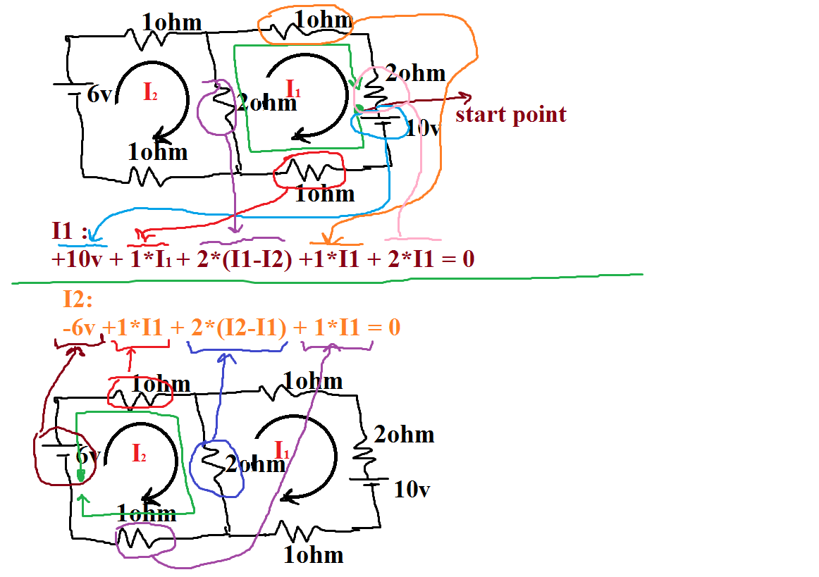
I offer you first remember this in analyses :

1- write the Polarity of component which you enter it when you loop . You're wrong in first loop is you write the 10v voltage source when you pass it

2- the middle resistor have 2 current I1 & I2 together . when you wanna write voltage of Common resistor between of two loop you should take positive (+) voltage for Intended loop and take negative voltage for which loop that your are not writing the equation for that ;

enter image description here

after this Ordered the equation you will have this 2 :

I1:

4I1-2I2 = -10


I2:

4I2-2I1= +6

and sorry for my bad english and bad painting ;)

\$\endgroup\$
0
\$\begingroup\$

Your approach looks right, however your sign convention is a little bit uncommon and could have led to an error.

The two mesh equations are:

(1) E1 + I1 R4 + I1 R3 - I2 R3 + I1 R2 + I1 R1 = 0

and

(2) -E2 + I2 R5 + I2 R3 - I1 R3 + I2 R6 = 0

Which leads to the mesh currents: I1 = -7/5 and I2 = 4/5.

This should help you to find the mistake.

\$\endgroup\$
5
  • \$\begingroup\$ How do you compute the third current using the given method? \$\endgroup\$ Commented Sep 4, 2016 at 14:07
  • \$\begingroup\$ Take a look at my answer for clarification :) \$\endgroup\$ Commented Sep 4, 2016 at 14:35
  • \$\begingroup\$ The current I3 = I2 - I1 = 3/5 A. But I3 is not a mesh current. \$\endgroup\$
    – Mario
    Commented Sep 4, 2016 at 14:39
  • \$\begingroup\$ I understand.I am used to mixing branch and mesh analysis for these problems. \$\endgroup\$ Commented Sep 4, 2016 at 14:42
  • \$\begingroup\$ @Mario Why I2 is negative ?? \$\endgroup\$
    – G36
    Commented Sep 4, 2016 at 14:46
0
\$\begingroup\$

I usually take this approach:

schematic

simulate this circuit – Schematic created using CircuitLab

After this I decide the direction of each current loop.By keeping the ones you chose:

\$E_1\$=\$I_1\$\$R_5\$+\$I_2\$\$R_3\$+\$I_1\$\$R_6\$ for the first loop
\$-E_2\$=\$I_3\$\$R_2\$+\$I_3\$\$R_1\$+\$I_3\$\$R_4\$-\$I_2\$\$R_2\$ for the second loop
And
\$I_1\$=\$I_2\$+\$I_3\$

Everything is chosen in an arbitrary way.If there is something wrong,the sign of the respective current will tell you.

This isn't mesh analysis,but it's a different approach.Who knows,you may have need of it in the future.

\$\endgroup\$
5
  • \$\begingroup\$ Isn't that a method for branch analysis while I am doing mesh analysis. \$\endgroup\$ Commented Sep 4, 2016 at 14:35
  • \$\begingroup\$ No, you are wrong IR3 = I2 - I1 \$\endgroup\$
    – G36
    Commented Sep 4, 2016 at 14:38
  • \$\begingroup\$ @G36 if you are referring to the direction of I3 then you are right.I assumed everything randomly and then,as I solved,I found out mistakes(that's how it's supposed to work,by looking at the signs).I thought I should leave Sara do the rest.Anyway,it looks like I mixed two different methods.I will edit my post. \$\endgroup\$ Commented Sep 4, 2016 at 14:48
  • \$\begingroup\$ Analysis with multiple mistakes as it stands. \$\endgroup\$
    – rioraxe
    Commented Sep 4, 2016 at 19:15
  • \$\begingroup\$ @rioraxe What are the mistakes now?The idea is to set everything in an arbitrary way (but still following some rules).Then as the calculations flow,you get some current with a - sign(but correct absolute value).Then you can correct this and go on.Different doesn't mean mistaken. \$\endgroup\$ Commented Sep 5, 2016 at 9:27
0
\$\begingroup\$

Your problem is just a matter of signs. Let's look at the schematic, with signs added:
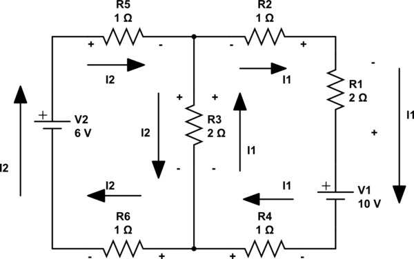
schematic

simulate this circuit – Schematic created using CircuitLab

If you look closely, you will see that the signs I placed around \$R_3\$ are different than the way you did it. You set up \$I_1\$ to go in the opposite direction than is conventional given the polarity of \$V_1\$. That's fine. There's no problem doing it that way. But if you do it that way, then you must arrange the signs correctly. Since the (-) end of \$V_1\$ touches \$R_4\$ on the right, that side of \$R_4\$ must be more negative than the other side. So you place the sign that way and also continue that process around the \$I_1\$ loop. I think you will see what I've done here makes sense now.

Now the same process is followed for \$I_2\$ and you can see how the left side of \$R_5\$ is more positive than the right side. And so I've also arranged the signs related to \$I_2\$, accordingly, around its loop as well.

At this point you can see that both currents result in a similar sign arrangement across \$R_3\$, and not an opposing arrangement. Therefore, the mathematical equations work out this way:

\$ \$

LOOP \$I_1\$:

\$-V_1+I_1\cdot R_4+\left(I_1+I_2\right)\cdot R_3 + I_1\cdot R_2 + I_1\cdot R_1 = 0\$

\$I_1\cdot\left(R_1+R_2+R_3+R_4\right) + I_2\cdot R_3 = V_1\$

\$6\cdot I_1 + 2\cdot I_2 = 10\$

\$3\cdot I_1 + I_2 = 5, \;\;\;\therefore I_2 = 5 - 3\cdot I_1\$

\$ \$

LOOP \$I_2\$:

\$V_2 - I_2\cdot R_5 - \left(I_1+I_2\right)\cdot R_3 - I_2\cdot R_6 = 0\$

\$V_2 = I_1\cdot R_3 + I_2\cdot \left(R_3+R_5+R_6\right)\$

\$6 = 2\cdot I_1 + 4\cdot I_2\$

\$3 = I_1 + 2\cdot I_2, \;\;\;\therefore I_2= \frac{3-I_1}{2}\$

\$ \$

This results in:

\$5 - 3\cdot I_1 = \frac{3-I_1}{2}, \;\;\;\therefore I_1 = \frac{7}{5}A\$

\$I_2 = 5 - 3\cdot I_1 = 5 - 3\cdot \frac{7}{5}, \;\;\;\therefore I_2 = \frac{4}{5}A\$

You can now estimate, for example, that the magnitude of the total current through \$R_3\$ will be \$I_1+I_2=2.2A\$. The direction of that conventional current will be from the shared (+) side to shared (-) side, or downward pointing.
\$\endgroup\$

Your Answer

By clicking “Post Your Answer”, you agree to our terms of service and acknowledge you have read our privacy policy.

Not the answer you're looking for? Browse other questions tagged or ask your own question.