0
\$\begingroup\$

How would I configure an op-amp to filter out the negative portion of a signal. Would it just be to put the negative supply of the op-amp to ground? I wish to do this with the 200MHz EL1801 op-amp to remove the negative sync from a 75 ohm RGB video signal which will be atleast 150MHz.

Datasheet: look for video sync remover on page 10

http://www.intersil.com/content/dam/Intersil/documents/el81/el8100-01.pdf

Application note: explains how to restore dc level.

https://www.intersil.com/content/dam/Intersil/documents/an95/an9514.pdf

\$\endgroup\$
5
  • \$\begingroup\$ just use active clamp during HS \$\endgroup\$
    – D.A.S.
    Commented Sep 7, 2016 at 17:42
  • \$\begingroup\$ Could you give me an example circuit? I'm new to electronics \$\endgroup\$ Commented Sep 7, 2016 at 17:44
  • \$\begingroup\$ Your solution might work if the input can take the negative voltages. Also, the output of the op-amp might not go all the way to GND if the output stage does not "pull" (active sink). I couldn't find the part you mention so I can't tell if these issues would be a problem for you. Can you post a link? \$\endgroup\$
    – Daniel V
    Commented Sep 7, 2016 at 17:45
  • \$\begingroup\$ I believe it goes within 50mV of each rail. Also it can handle -0.3v less than Vs- for input. The sync goes from 0 to -0.3v. It says you can use this opamp to remove sync but does not explain how to do it. \$\endgroup\$ Commented Sep 7, 2016 at 17:48
  • \$\begingroup\$ do you have sync separator signal? series C and FET to gnd controlled by HSync to DC restore and remove sync tip or comparator to Vref to detect neg sync and clamp output with series R \$\endgroup\$
    – D.A.S.
    Commented Sep 7, 2016 at 18:10

2 Answers 2

1
\$\begingroup\$

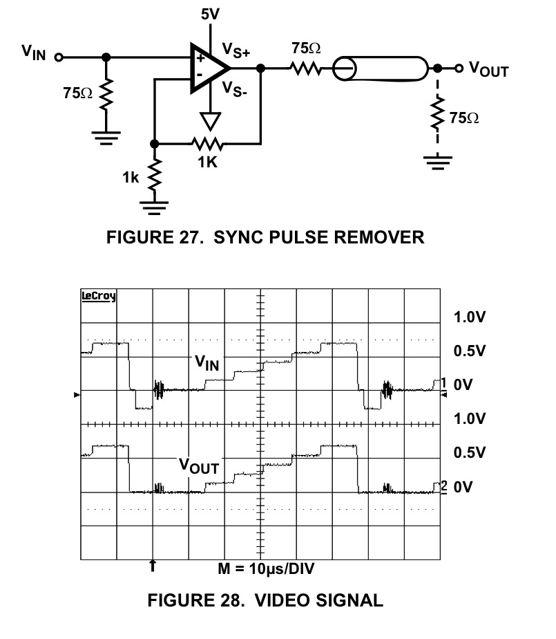
This seems clear in datasheet using single supply.

enter image description here

This assumes front porch input is clamped to 0V and neg. sync tip gets clipped by 0V rail.

\$\endgroup\$
6
  • \$\begingroup\$ This clamps chroma burst as well. Also, assuming front porch clamped to 0V just means adding some more electronics ahead. Video input as to be able to cope with AC coupled sources. \$\endgroup\$
    – carloc
    Commented Sep 7, 2016 at 19:47
  • \$\begingroup\$ RGB does not use chroma burst, which I assumed from OP's other recent questions \$\endgroup\$
    – D.A.S.
    Commented Sep 7, 2016 at 19:50
  • \$\begingroup\$ Oh yes you are right, I overlooked this. Anyway clamp/DC restorer needed ahead is still a big issue, without it input 0V will be varying as per average value of video and hence changing with picture brightness. Just to make clear to @Omar Mahmood that Fig.28 circuit alone could not do the job. \$\endgroup\$
    – carloc
    Commented Sep 7, 2016 at 20:09
  • \$\begingroup\$ I was just unsure if i should use ground because it said the output could swing -0.3v on 75 ohm impedance. This was what was confusing me. But now that's been cleared. So after this I need a way to restore to 0v correct? \$\endgroup\$ Commented Sep 7, 2016 at 20:20
  • \$\begingroup\$ no. I must be DC coupled going in or clamped to 0V at front porch. \$\endgroup\$
    – D.A.S.
    Commented Sep 7, 2016 at 21:14
2
\$\begingroup\$

How would I configure an op-amp to filter out the negative portion of a signal.

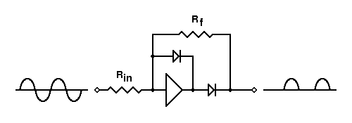
Just use a precision half-wave rectifier circuit: -

enter image description here

This one also inverts so to keep the positive half of the signal whilst discarding the negative half, preceed the recision rectifier with a normal inverting op-amp stage.

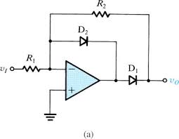
You will probably need to choose an op-amp with a gain-bandwidth product that is 10 times that of your signal to get reasonable fidelity. Below is a slightly more informative circuit showing both input pins: -

enter image description here

And yes, as Scott has pointed out in a comment a small capacitor across D2 usually helps (about 1 pF to 10 pF is a good starting value.

\$\endgroup\$
3
  • \$\begingroup\$ Circuits like that often need a small cap in the feedback loop. \$\endgroup\$ Commented Sep 7, 2016 at 17:58
  • \$\begingroup\$ While this would work, I'm unsure of which components I would need. I don't think there is really any video op-amp which output a 10+ gain without sacrificing fidelity \$\endgroup\$ Commented Sep 7, 2016 at 18:03
  • 1
    \$\begingroup\$ Use a high speed op-amp with GBWP of over 1 GHz - there are a few about. \$\endgroup\$
    – Andy aka
    Commented Sep 7, 2016 at 18:06

Your Answer

By clicking “Post Your Answer”, you agree to our terms of service and acknowledge you have read our privacy policy.

Not the answer you're looking for? Browse other questions tagged or ask your own question.