14
\$\begingroup\$

Sorry this is such a silly question, but I can't seem to understand this. In the third diagram here it shows a pull-up resistor.
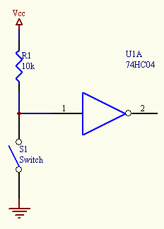
enter image description here

I understand that when the switch S1 is closed, current is pulled down to ground and assumes a value of 0. This doesn't short because of the resistor limiting the current.

My question is: When the switch is open and the current is flowing into the input pin of the device, how does it pick up that this is a high value and not a low value? Wouldn't the resistor limit it to the extent that it would be .0005 A and so it would barely register with the device?

EDIT: Also, I am just looking at the pull-down resistor case on the same page. Why does the first switch not short when it is directly connected to VCC, there is no resistor, and the switch is open? Isn't this a no-no? I can't really grasp what is going on with the pull-down resistor.

\$\endgroup\$
1
  • 3
    \$\begingroup\$ I am only beginner in this, and I would expect all this "magic" can be described by impedances. \$\endgroup\$
    – Al Kepp
    Commented Jan 26, 2012 at 17:15

2 Answers 2

19
\$\begingroup\$

The input is high-impedance and as such hardly draws any current. But let's, for sake of argument, pretend there flows a (rather large) current of 1\$\mu\$A. This current will flow through the 10k\$\Omega\$ pull-up resistor causing a 10mV (1\$\mu\$A \$\times\$ 10k\$\Omega\$) voltage drop across it. So in this case the voltage on the input pin will be \$V_{CC}\$ - 10mV, probably 5V - 10mV = 4.99V. That will be still recognized as a high level, so no problems here.
The 10k\$\Omega\$ is a typical value for pull-up resistors for this reason: even if there's a small leakage current the voltage drop is negligible. Don't be tempted to increase it to 1M\$\Omega\$, though it will decrease the current when the switch is closed. At 1\$\mu\$A leakage current the voltage drop will be 1\$\mu\$A \$\times\$ 1M\$\Omega\$ = 1V, and then the 5V will drop to 4V. For a 5V supply this will still be OK, but for a 3.3V supply the resulting 2.3V may be too low to be always seen as a high level.

For the pull-down the story is about the same. There doesn't flow any current in the input; you can't say that it would be connected to ground (in which case closing the switch would indeed cause a short-circuit). As such the input takes the voltage you apply to it. If the switch is closed this is \$V_{CC}\$. If the switch is open it's ground (through the pull-down resistor). If there's no current flowing (ideal world) then there's no voltage drop across the resistor either, and the input will be at \$GND\$ level. In a real world situation it may be a few mV.

\$\endgroup\$
3
  • 2
    \$\begingroup\$ Just a suggestion: the site he linked is working with TTL voltage (5V), maybe it's better to keep values consistent \$\endgroup\$
    – clabacchio
    Commented Jan 26, 2012 at 16:33
  • 4
    \$\begingroup\$ In many applications, leakage currents will be well below 1uA and a 1M resistor would be just fine; in battery-powered applications, if the switch will be closed much of the time, a 10K resistor could waste an objectionable amount of power, but a 1M resistor would only draw 1/100 as much. When using a 10K resistor, if one blindly assumes that leakage currents will be below 100uA, one will usually be correct even in the presence of board contamination and high humidity. It's not generally safe to assume leakage currents will be below 1uA, but one can often make them be that low if needed. \$\endgroup\$
    – supercat
    Commented Nov 15, 2012 at 17:58
  • 2
    \$\begingroup\$ To push a 1uA through a 1M ohm resistor you would need a damn kilo-volt. Not sure how you intend for a 5V supply to drop a whole volt across a 1M resistor when the current in the circuit is going to be like 0.005uA... \$\endgroup\$ Commented Jun 12, 2019 at 23:10
16
\$\begingroup\$

I think you've misunderstood a concept: the input of the gate (in this ideal case) is like an open circuit, so it doesn't absorb any current, it just senses the voltage. So the simplest thing is to consider the leftmost part of the circuit without the gate, see what happens at the node 1, and then apply the voltage to the gate input.

When S1 is open, no current is flowing on R1, that means no voltage drop, and the input of the gate will be at the high level.

When S1 is closed, it connects the lower end of the resistor to the ground, and with it also the input of the gate. The resistor will have now a 5V voltage drop, that will cause a current of value given by:

$$ I= {V_R \over I_R} = {5 \over 10^3} = 0.5 mA = 500 \mu A $$

It's important to note that the current will flow only through the resistor and the switch, from Vcc to Ground, while no current will flow into the input of the gate.

About the pull-down, is the same concept: if the switch is open, you don't have any current, so the resistor won't have a voltage drop, and the voltage at the top of it will be also 0V.

And just as a side note, 0.0005 Ampères is still 0.5 mA, and is not negligible in many cases.

\$\endgroup\$
1
  • 1
    \$\begingroup\$ "When S1 is open, no current is flowing on R1, that means no voltage drop, and the input of the gate will be at the high level." This sentence made all the difference. Now I understand pull up/down resistors \$\endgroup\$
    – Steve
    Commented Feb 26, 2016 at 18:10

Your Answer

By clicking “Post Your Answer”, you agree to our terms of service and acknowledge you have read our privacy policy.

Not the answer you're looking for? Browse other questions tagged or ask your own question.