1
\$\begingroup\$

I am building a project that will lock several cabinet doors using ULN2003AGP chips and security electro magnets similar to this:

AGPtek® 60kg 130LBs Holding Force Electric Magnetic Lock

This magnet has a max current draw of 150ma, which is well below the 500ma that each ULN2003 channel limit. My plan was to attach six magnets to a single chip, which should draw a max of 900ma, which is also well below the max current limit for the entire chip. (note, my power supply is a box-plug 12v 3A supply.) My design is shown below. (showing 1 of the 6 connected magnets)

These magnets will typically stay on for hours, then turn of for some amount time between 1 and 30 minutes. All of them will spend at least an hour on, all at the same time.

My original plan was to power 9 magnets using 2 ULN2003 chips. However, after connecting one magnet to one chip and two magnets to another chip, I returned a week later to find that the current flowing through each circuit had fallen significantly (the magnets no longer functioned.) Initial investigation (without a multi-meter) showed that the transistor array was not functioning correctly (though in hindsight, I did not rule out the optocoupler.) Do I need to remove the 100nf caps, add diodes, or modify the way the optocoupler is connected? Is there another, better way to connect electromagnets to a ULN2003 chip?
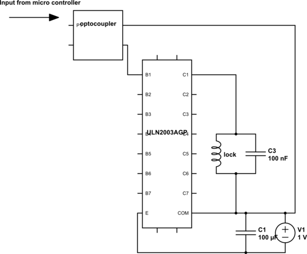
schematic

simulate this circuit – Schematic created using CircuitLab

\$\endgroup\$
14
  • \$\begingroup\$ Did you measure voltages? \$\endgroup\$ Commented Sep 15, 2016 at 20:04
  • \$\begingroup\$ Not yet, I did not have a volt meter on hand when I last visited the installation. I will be going back there in two days. \$\endgroup\$
    – Hoytman
    Commented Sep 15, 2016 at 20:06
  • 2
    \$\begingroup\$ And what is dutycyle, i.e. on time of each magnet vs. rest time? Are they operated one by one or all of them could be powered at the same time? Each magnet draws 150mA, this will drop around 1.2V on darlington's CE. Total 6x1.2Vx150mA=1.1W, thermal resistance is given as just below 70 K/W so chip temperature rise is some 70 to 80 Celsius. Definitevely too much for reliable 100% dutycyle operation. \$\endgroup\$
    – carloc
    Commented Sep 15, 2016 at 20:22
  • 1
    \$\begingroup\$ Read the data sheet carefully, the ULN2003 SO version is good for maybe 100mA per output 100% duty cycle at 70°C with 6 outputs on. \$\endgroup\$ Commented Sep 15, 2016 at 20:33
  • 2
    \$\begingroup\$ I think you will find that you have neglected to check in rush. I have measured a typical maglock with a 200mA or so typical current draw had a just over 1A inrush current peak. You might have let the smoke out, I know I did. \$\endgroup\$
    – D-on
    Commented Sep 15, 2016 at 21:20

2 Answers 2

1
\$\begingroup\$

Your optocoupler input is somewhat lacking.

To all intents and purposes an optocoupler is an NPN transistor. It's just controlled by light instead of base current. Change the input circuit to be more like:

schematic

simulate this circuit – Schematic created using CircuitLab
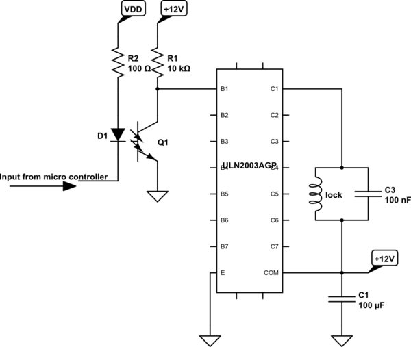
(I have replaced your box with an actual transistor and LED so you can see better how it works).

When the output is HIGH (i.e., at VDD) the LED is off. That means the NPN is off. The resistor R1 pulls the base of the darlington pair high, which turns on the coil.

When the output is LOW (i.e., near 0V) the LED turns on. With the LED on the NPN is on. That pulls the base of the darlington pair down to ground, turning off the coil.

The way it's wired is a kind of double-inversion. The LED does the opposite to normal (on is LOW, off is HIGH) and the NPN in the optocoupler switches the darlington pair the opposite of how you would normally think to do it. The two together result in normal operation.

Yes, it is possible to use the NPN as a high-side switch, in which case you could invert the LED so it was on when HIGH, and use a pull-down instead of a pull-up, but I apply the same rule to optocouplers that I apply to all transistors when using them as switches: NPN are emitter direct to ground, PNP are emitter direct to power.

\$\endgroup\$
6
  • \$\begingroup\$ I'm curious, is that transistor rule a convention related to digital circuit design or is there a physical property that improves function? \$\endgroup\$
    – Hoytman
    Commented Sep 15, 2016 at 20:40
  • \$\begingroup\$ @Hoytman: The voltage across the B-E junction for normal BJTs is about 0.7V, positive for NPN, negative for PNP. The system should be designed with that in mind. (Although basic optocouplers are fully floating and so don't really need to follow that.) \$\endgroup\$ Commented Sep 15, 2016 at 20:51
  • \$\begingroup\$ Would my current optocoupler layout be responsible for the failure over time? \$\endgroup\$
    – Hoytman
    Commented Sep 15, 2016 at 22:56
  • \$\begingroup\$ @Hoytman Well, with no pulldown resistor on the base, when the optocoupler is off the input is floating - and that can lead to all sorts of strange things happening. \$\endgroup\$
    – Majenko
    Commented Sep 15, 2016 at 23:00
  • \$\begingroup\$ Thanks for the notes, what does fully floating mean? \$\endgroup\$
    – Hoytman
    Commented Sep 16, 2016 at 19:21
1
\$\begingroup\$

Do you really need parallel control of the inputs? Or can you do things with a simple SPI interface?

The TI TPIC6595 product brief is a fabulous serial-to-parallel shift register with 8- beefy MOSFET output drivers. These are good for 250 mA continuous (1.5A peak) and have built-in avalanche clamps at 60 Volts for dealing with solenoid-type magnetic devices. No back-EMF diodes needed.

The easiest interface requires 3 signals: Clk, Data, Strobe. There is much working code published on the web that will get you going faster.

Vcc is 5V and the devices don't work from a 3.3V rail. But it's easy to interface the control signals to 3.3V devices.

I still use the uln2003 / 2004 devices but most of my designs now use the TPIC family of power shift-registers.

\$\endgroup\$
2
  • \$\begingroup\$ This looks like a great solution for next time. \$\endgroup\$
    – Hoytman
    Commented Sep 17, 2016 at 4:15
  • \$\begingroup\$ However, The input is coming from several different sources, not just one controller. \$\endgroup\$
    – Hoytman
    Commented Sep 18, 2016 at 4:45

Your Answer

By clicking “Post Your Answer”, you agree to our terms of service and acknowledge you have read our privacy policy.

Not the answer you're looking for? Browse other questions tagged or ask your own question.