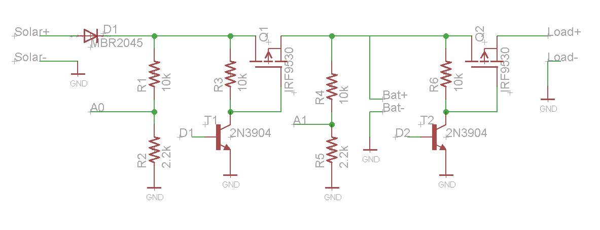
I designed a solar charge controller using arduino and MOSFET IRF9530. Main purpose was to charge 12V 7aH battery and then control the load. Here load is a solar blinker which needs 12v and around 1Amp. Following is the schematic of the circuit. The circuit is working fine.
In the above circuit, resistor R1 R2 are used as voltage divider to sense the solar voltage by reading the analog values of A0 pin. If the solar voltage is good, then digital pin D1 is turned on, so MOSFET conducts solar volts to battery and battery starts charging. By reading the analog values at A1 pin, we can read the battery voltage and if battery voltage is good then turning on the digital pin D2 will start the load.
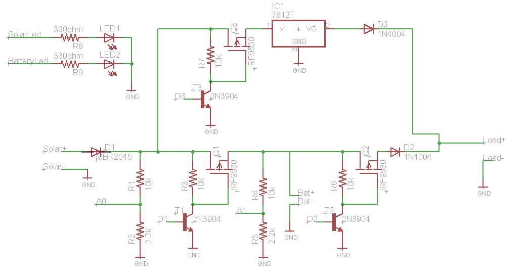
Later on I thought of modifying the circuit in such a way that if the sun light is good and we are getting enough voltage from panel, then turn on the load using solar voltage and keep charging the battery. If there is no sunlight & battery has enough voltage, then the load will be using battery voltage. So I made the following changes:
Changes which I have done is that I added another pair of transistor and mosfet and connected them to digital pin3. SO if there is a good solar voltage and I want to turn on the load using solar voltage then I will make the D2 low and D3 high so solar volts will be given to the load via 7812 because I don't want to give higher voltages like 19-20v to the load. If there is no sunlight, then D3 will be low and D2 will be high to give battery voltage to load. I have used the diode D2 D3 to block the voltage.
To control the switching of load between solar and battery voltage, I have written folling code in arduino:
if(solVolt > 14 )
{
 //Its a bright day & we are receiving full sunlight
 //so turn on the load using solar voltage
 digitalWrite(solarLoadPin,HIGH);
 digitalWrite(batteryLoadPin,LOW);
 digitalWrite(solarLed, HIGH);
 digitalWrite(batteryLed, LOW);
}
else if(solVolt < 12 && batVolt > 12.4)
{
 //Its a dark night and we are not receiving sunlight
 //so turn on the load using battery voltage
 digitalWrite(solarLoadPin,LOW);
 digitalWrite(batteryLoadPin,HIGH);
 digitalWrite(solarLed, LOW);
 digitalWrite(batteryLed, HIGH);
}
else if(batVolt <= 10.8)
{
 digitalWrite(batteryLoadPin,LOW);
 digitalWrite(batteryLed, LOW);
}
Now I have few questions regarding this design:
Is this circuit fine? I tested the circuit by first plugging only battery and load. So the load was on and working fine. Battery Led was on showing load is using battery. But as soon as I plug in panel, it didn't switch to the solar voltage. I unplugged everything and then plugged in panel and battery so the load was on and using the solar voltage but the voltage was very low while the voltage from the solar panel was 18-19v.
Battery not charging? I unplugged the load and only allowed battery to charge. Battery volts at that time was 12.44 but instead of charging, voltage reduces to 12.40
Solar voltage vs current? There was very low sunlight and the panel was still showing 18v. I think it should show low voltage, around 12v when there is not a bright sunlight. But its voltage was high. So does that means, its output current will be low in this situation as Power = volts x amps. So if volts is high, amps will be low.
Basically I need to design the circuit which automatically switch between solar voltage and battery voltage depending upon the conditions of the day and night.

