1
\$\begingroup\$

In order to measure voltage with an Ammeter, the current through the impedance of the Ammeter is measured and the voltage is determined indirectly. In the circuit below the impedance of the Ammeter is \$ R_2 + L_1 \$. The resistor \$ R_1 \$ is there to limit the error in current for a temperature dependent \$ R_2 \$.

Now I want to compensate the frequency dependency of this circuit. For that \$ C_1 \$ is added in parallel to \$ R_1 \$, which I want to calculate.

$$ \frac{\underline{V}_1}{\underline{V}_m}=\frac{R_1||\underline{X}_c}{R_2+\underline{X}_L}+1=\frac{\frac{R_1}{1+iwR_1C}}{R_2+iwL}+1=\frac{R_1}{R_2+iwR_1R_2C+iwL-w^2R_1CL}+1 $$

If all the terms holding a \$ w \$ cancel out, I actually would get a frequency independent circuit.

$$ iwR_1R_2C+iwL=w^2R_1CL $$

But that seems like an impossible task. How could two complex numbers add up to a real one? What am I doing wrong?
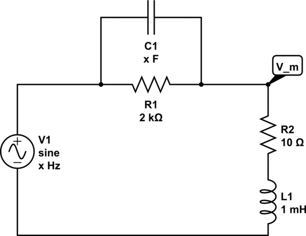
schematic

simulate this circuit – Schematic created using CircuitLab

\$\endgroup\$

2 Answers 2

1
\$\begingroup\$

What am I doing wrong?

Adding C1 to the circuit makes a complex series resonant circuit and doesn't look like it will ever work.

If you want to make the transfer function constant across frequency then you need to add an inductor (L2) in series with R1 such that the scaling of L2 is R1/R2 times bigger than L1.

In your particular circuit L2 would be 200 mH.

\$\endgroup\$
1
  • \$\begingroup\$ Yes, your frequency-compensation is correct. However, the real goal is to compensate circuit current, which is a point that was missed in the question. Your proposed frequency compensation kills circuit current for higher frequencies. \$\endgroup\$
    – glen_geek
    Commented Sep 27, 2016 at 14:58
0
\$\begingroup\$

Your frequency compensation scheme can indeed add a little to the top-frequency end (in the example circuit you've provided). Your error is in solving for V_m. If R2 and L1 represent the ammeter internals, then you must optimize current through these components.
For your example circuit, a C1 value of 104 pf provides a slightly extended frequency response. This solution should be used with caution, because it assumes that the voltage source you're measuring is indeed a perfect voltage source, having no resistance of its own, nor any reactance.
Note that for certain other circuit parameters. Andy_aka is right, no solution exists.

\$\endgroup\$

Your Answer

By clicking “Post Your Answer”, you agree to our terms of service and acknowledge you have read our privacy policy.

Not the answer you're looking for? Browse other questions tagged or ask your own question.