2
\$\begingroup\$

please bear with me as I am very new to electronics. I am trying to connect a NodeMCU dev kit (ESP8266) with a 1602LCD. I am using an i2c converter to interface with the LCD. The LCD requires 5V. I think the nodemcu dev kit (esp8266), uses 3.3v for it's digital outputs but it does have a VIN on the module so it regulates that 5V to 3.3v internally. I bought a logic level converter because I read that I would need one.

The LCD however works fine without the logic level converter so I am confused. Does this mean it is safe to use it as is? I googled on how to connect a bi-directional logic level converter but I am confused about the power connections.

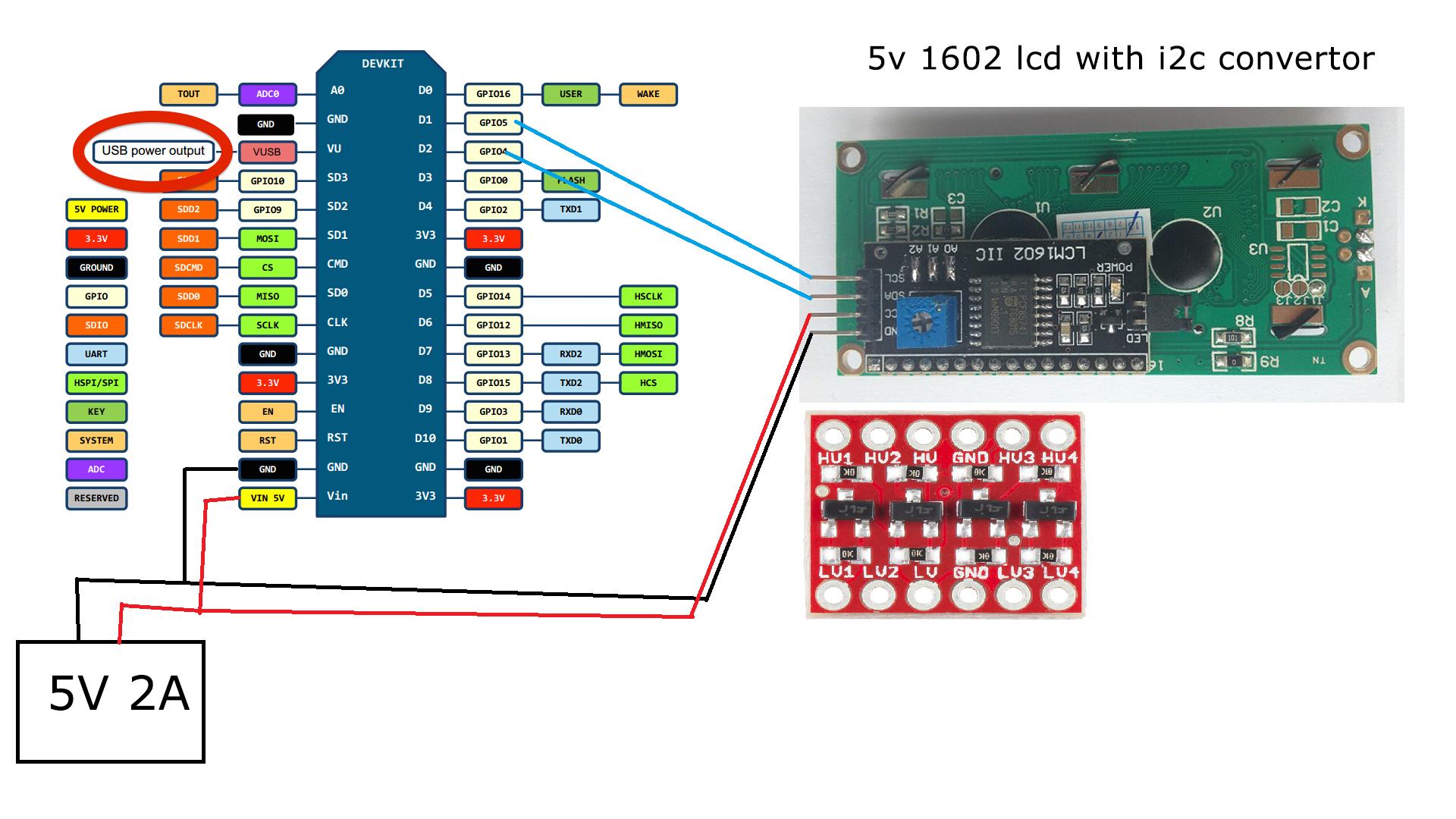
This is how my circuit looks right now: enter image description here

How should I connect the bi-directional logic level converter (if needed) ?

Also, Would it be possible to add three 5mm leds to this circuit with the power source I am using? I am not sure which resistors to use because I just want to use the LEDs as power indicators and it doesnt have to be bright.

Any help would be greatly appreciated.

\$\endgroup\$

2 Answers 2

4
\$\begingroup\$

I am not an electronics engineer... that being said, I have used a 1602 LCD screen with my Orange PI Zero, which, like your ESP, also outputs SDA and SCL at 3.3V (and not the 5V expected by the 1602). Just like in your setup, the screen appears to work perfectly - that is, provided it is fed with 5V at its VCC pin. EDIT: But keep reading - in the end, it turned out that it wasn't "working perfectly"...

To be 100% sure, you'd use your level shifter as follows:

  • Connect the two GNDs of the shifter to any of your ESP's GND pins
  • Connect 3.3V from the ESP to the "LV" of the shifter
  • Connect 5V to the "HV" of the shifter.
  • Connect the SDA and SCL pins of your ESP to two "LV"s of the shifter (e.g. LV1 and LV2)
  • Connect the corresponding HV pins to the SDA and SCL of the screen (e.g. HV1 and HV2).

That should work - and give you peace of mind that the screen is not slowly frying the electronics of your ESP.

I should probably follow my own advice and do the same for my very similar Orange PI Zero setup :-)

EDIT: Updated, a week later:
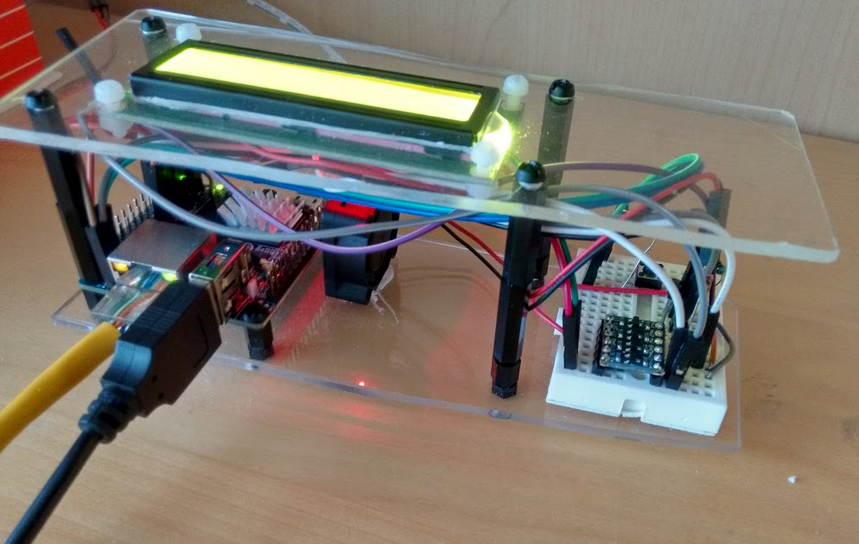
My Orange PI Zero setup with the 1602

I bought a 4-channel level shifter from ebay (I don't post the link for fear of being classified as a spammer). Very cheap - 1.5 Euros - and 1 Euro for shipping to the NL (which took two days to arrive from France). In fact, I bought two of the shifters - having a spare is always good policy :-)

I soldered the headers and connected the shifter as I described above; and everything worked fabulously. Curious to see what was the actual impact, I also used my scope to see the level of SDA and SCL before and after the use of the shifter. It turned out that when I was connecting the Orange PI Zero's SDA/SCL directly to the screen's SDA/SCL, the level was pulled up to 3.9V - that is, above the 3.3V that the GPIO pins should be...

It wasn't 5V - but then again, it wasn't 3.3V either. I am guessing the I2C circuit that is attached to the 1602 causes some voltage drop of its own - taking it down to 3.9V. But the important thing is that the end result was 3.9V on the SDA and SCL pins of the Orange PI Zero - above 3.3V... Instead, with the shifter in place as described above, the values are now exactly right: both SDA and SCL are at 3.3V.

I do feel safer about my PI now :-)
\$\endgroup\$
3
  • 1
    \$\begingroup\$ Just FYI, I'll explain the 3.9V which you measured: "I am guessing the I2C circuit that is attached to the 1602 causes some voltage drop of its own - taking it down to 3.9V." Not quite correct :-) The I2C interface attached to the 5V LCD screen, was pulling-up the I2C signals via resistors to 5V. However the GPIO on the Orange Pi is (nominally) 3.3V (3.6V max). Then a little above that, the ESD protection structures of the SOC's pins will start to conduct current and limit the input voltage (until they burn out!). You were lucky the 5V I2C signals were current-limited by the pull-up resistors. \$\endgroup\$
    – SamGibson
    Commented Jul 14, 2017 at 13:01
  • 1
    \$\begingroup\$ The Orange Pi SOC datasheet linked here might be useful: Max voltage on GPIO pin - Orange Pi forum. There are previous discussions here on Stack Exchange about allowing current to flow through ESD protection structures inside ICs (which can be similar to, but don't have to be, diodes to the supply rails), especially high currents or even low currents for extended periods. So it is good that you noticed the problem and fixed it. It was a good idea to use the 'scope to check any signals which you were unsure about. \$\endgroup\$
    – SamGibson
    Commented Jul 14, 2017 at 13:05
  • 1
    \$\begingroup\$ @SamGibson: Thanks, Sam - learned a lot from your comments (they triggered further reading on ESD protection). \$\endgroup\$
    – ttsiodras
    Commented Jul 15, 2017 at 13:18
0
\$\begingroup\$

How should I connect the bi-directional logic level converter (if needed) ?

the best way to translate is not to translate at all. you should explore if you can run your host at 5v or run your lcd at 3.3v - i'm staring at a 1602 running at 3v right now.

the trick there is to produce Vlcd sufficiently negative (vs. Vdd, typically in the 4 - 5v range). there are numerous ways to do that. For example a charge pump powered by a pulse train generated by your host.

short of that, try to use a resistor - they are quite simple and reliable as a translater.

if that doesn't work, there are lots of translators - from discrete versions (NXP has an application note on that) to ICs.

\$\endgroup\$

Your Answer

By clicking “Post Your Answer”, you agree to our terms of service and acknowledge you have read our privacy policy.