2
\$\begingroup\$

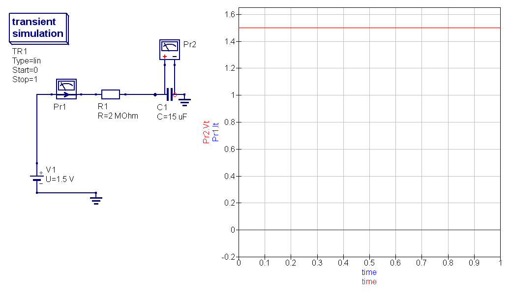
Hi I have just started to learn electronics. In order to understand the RC constant I have built the following very simple circuit in QUCS simulator.

According to the formula

RC time constant = R x C = 2,000,000 ohms x 0.000015 farads = 30 seconds

I would expect the graph of voltage on capacitor C1 rise steadily till it reaches 2/3 of 1.5 after 30 secs . However as it can be seen the the simulation shows straight graphs of both current and capacitor's voltage without any difference in time.

Can someone explain these results

\$\endgroup\$
2
  • \$\begingroup\$ Did you try delaying the turn-on of the voltage source? \$\endgroup\$ Commented Oct 3, 2016 at 17:11
  • \$\begingroup\$ @IgnacioVazquez-Abrams Can you please explain what is this? Have a mercy I am completely novice at this. \$\endgroup\$
    – Boris
    Commented Oct 3, 2016 at 17:12

4 Answers 4

5
\$\begingroup\$

The circuit simulator is solving for the steady-state initial condition before running the transient sim.

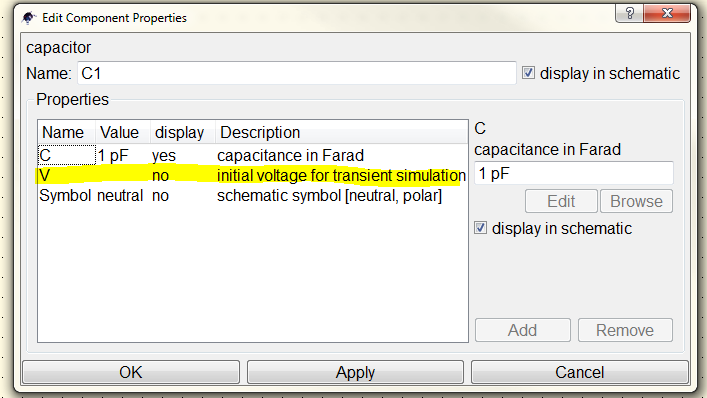
To get your desired behaviour you have to explicitly tell the simulator you want zero volts across the cap at t=0. To do this, double click on the part and set the initial voltage to zero - I've highlighted the line you need to change in the dialog below.

Qucs Capacitor Dialog box

\$\endgroup\$
2
  • \$\begingroup\$ Worked as a charm... I cannot accept it as an answer immediately. Becuase it says to wait for 8 more minutes. Thanks!!! \$\endgroup\$
    – Boris
    Commented Oct 3, 2016 at 17:17
  • \$\begingroup\$ @PeterK Dear Peter, I was wondering, would you be so kind to have a look at this post if time allows: electronics.stackexchange.com/questions/378429/… Thanks in advance. \$\endgroup\$
    – user929304
    Commented Jun 7, 2018 at 7:34
3
\$\begingroup\$

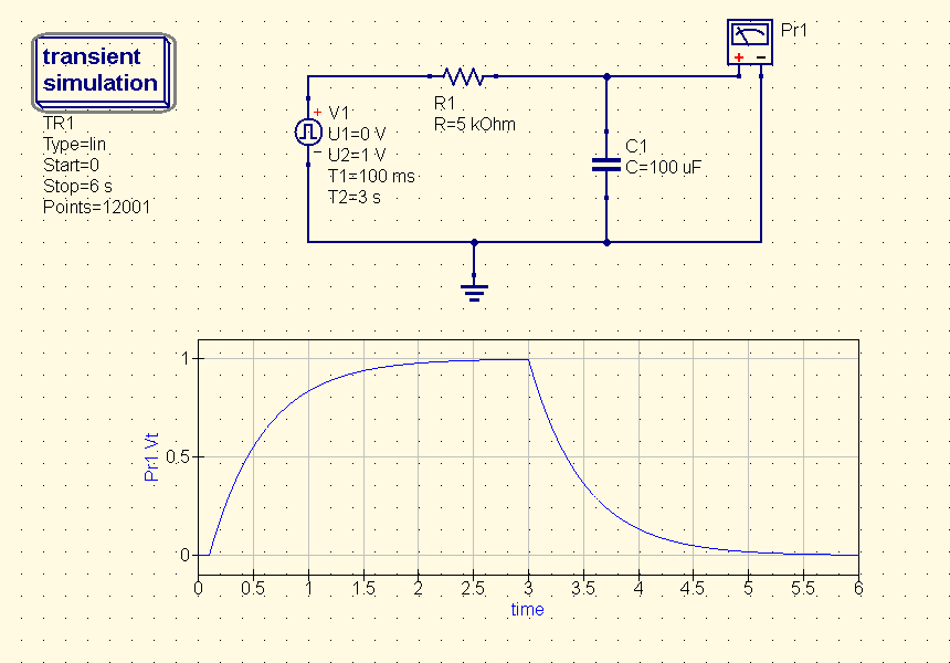
To simulate charging and discharging a capacitor, we use a voltage pulse. capacitor circuit

\$\endgroup\$
0
2
\$\begingroup\$

I have had this same issue.

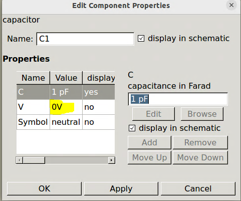
I had to set the initial value of the capacitor as mentioned by Synchrondyne. enter image description here

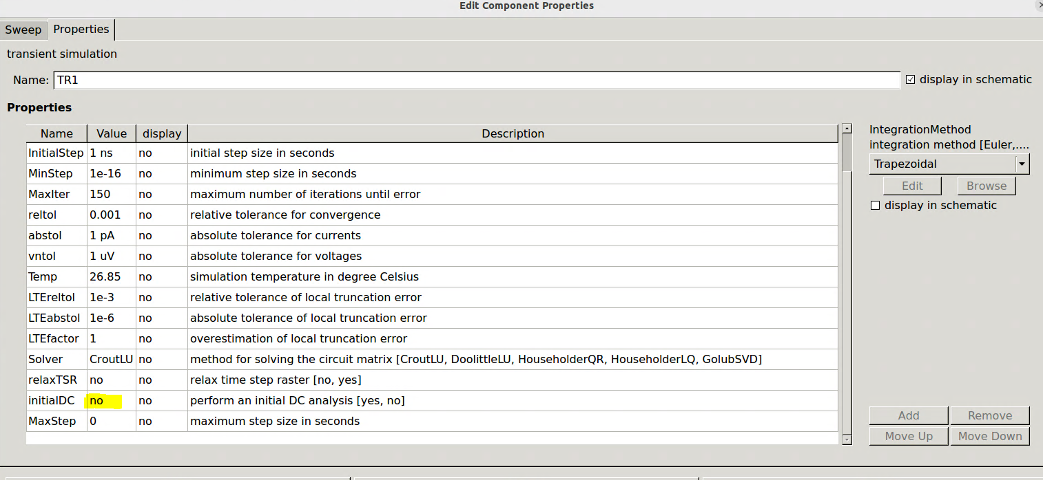
However I also had to turn off the InitialDC calculation of the Transient simulator object. To do this

  1. Double click the "Transient Simulation" object.
  2. Go to the properties Tab
  3. Find the "InitialDC" property and set it to "No"

enter image description here

\$\endgroup\$
2
  • \$\begingroup\$ Tried that as well and then Spice calculated an awful long time and then Spice reported it crashed. \$\endgroup\$ Commented Nov 8, 2023 at 21:10
  • \$\begingroup\$ @JohannesLinkels I can not recreate that, but I could take a guess. Seems like something is causing the simulation not to finish or run forever. Perhaps check that your minStep size is not too small and not zero. Maybe if it is too small it takes forever. It might also be good to check that the Stop time is not too long as well, since that could also cause it to run very long. \$\endgroup\$ Commented Jun 14 at 13:30
1
\$\begingroup\$

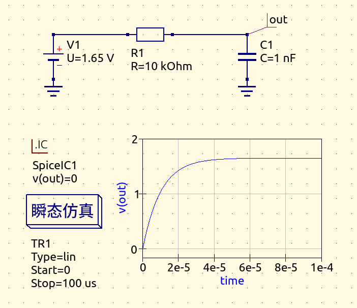
use .IC Section in the SPICE specific sections can help. I found that setting the initial voltage for the capacitor doesn't work at all.

ps: The software I use is qucs-s instead of qucs.

enter image description here

\$\endgroup\$
1
  • \$\begingroup\$ You are totally correct. In QUC-S setting the intitial voltage doesn't do a thing. By adding the .IC parameter I was able to set an initial condition. \$\endgroup\$ Commented Nov 8, 2023 at 16:17

Your Answer

By clicking “Post Your Answer”, you agree to our terms of service and acknowledge you have read our privacy policy.

Not the answer you're looking for? Browse other questions tagged or ask your own question.