3
\$\begingroup\$

I've selected a potential latching relay for use in a project (switching mains power), but - having been away from electronics for a while - I'm still trying to wrap my head around a couple things. Here's the relay in question:

http://www.digikey.com/product-detail/en/te-connectivity-potter-brumfield-relays/7-1393239-7/PB2014-ND/4925213

1) It says it's rated to 3V. Will 3.3v (my microcontroller (ESP8266) voltage) hurt it?

2) There's no way my microcontorller can source (or sink) enough power to drive this. It needs a 30ms pulse (minimum) at 3V with 21Ω of resistance. If it was NOT a latching relay, I could simply set up a transistor and call it a day - however, I'm not sure how to configure it for this. I know that I'll have to hook up two IO, and drive one HIGH and one LOW (A to HIGH, B to LOW or B to HIGH, A to LOW) for the duration of the pulse in order to switch the "latch" of the relay. Seeing as the IO pins themselves can't source or sink enough power, how do I configure transistors to turn HIGH or LOW depending on the IO? Goodness, I feel like I'm missing something super obvious.

3) Does anybody spot any immediate problems with my idea to use this to switch a mains power line?

Thanks!

\$\endgroup\$

3 Answers 3

2
\$\begingroup\$
  1. 3V is the coil voltage. You need to put a resistor in series with a coil to get the correct voltage. Use coil resistance and voltage divider equation to find the resistor value.

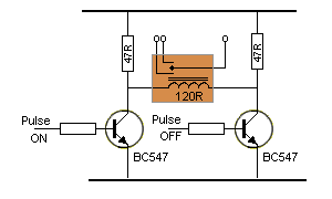
  2. Here's a typical circuit for driving a latching relay: enter image description here

    Obviously, ensure that the transistors are only turned on for a short amount of time, as they will sink reasonable current.

  3. The relay contact is rated for mains voltage, so no problem.

\$\endgroup\$
8
  • \$\begingroup\$ This is perfect, thanks so much! I assume that the resistor labeled "47" would be replaced with the calculated value? For my relay, I show 21Ω, so to drop 3.3v to 3, I calculate 210Ω? (Did I do it right?) Looking at the diagram, I'm pretty sure I understand how the driver works - however I'm rubbish at selecting a transistor. Any pointers there? \$\endgroup\$
    – Helpful
    Commented Oct 4, 2016 at 20:13
  • \$\begingroup\$ @Helpful Well, the "set voltage" is 2.1V, so you don't have to go all the way to 3V. 21 is the lower resistor, so you need more like 2.1R to get 3V. \$\endgroup\$
    – Armandas
    Commented Oct 4, 2016 at 20:18
  • \$\begingroup\$ Ah, I see - i was doing the calculations backward. Can you give some pointers toward transistor selection? Thanks. \$\endgroup\$
    – Helpful
    Commented Oct 4, 2016 at 20:24
  • 3
    \$\begingroup\$ Sorry, this is not perfect, and is in fact wrong. The set and reset voltages are simply the minimum voltages required to operate reliably, in this case 2.1 and 1.7 volts. The relay drive circuit should be designed for 3 volts, not the set voltage. However, the circuit shown ought to work. \$\endgroup\$ Commented Oct 4, 2016 at 20:27
  • 1
    \$\begingroup\$ @WhatRoughBeast I always thought that the rated voltage was a limiting value, but it looks like I was wrong. Thanks for pointing that out. \$\endgroup\$
    – Armandas
    Commented Oct 4, 2016 at 20:43
3
\$\begingroup\$

I see you are still looking at these DC relays. Nice choice, actually. You can select either one coil, or two. The two-coil version would be a bit easier. The one-coil version will require what amounts to a kind of H-bridge (or in amplifier terms, bridge-tied load) configuration. So I get why you are struggling.

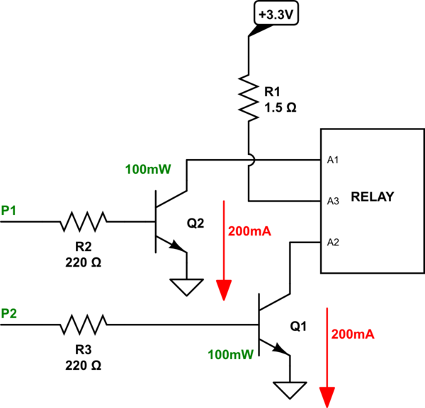
Let's start with the two-coil variety, as that is much easier:

schematic

simulate this circuit – Schematic created using CircuitLab

That's one way of handling it. Note that the BJTs can be small signal, it seems. But they should be rated for perhaps \$400\:\textrm{mA}\$ or better, just in case. This will require \$10\:\textrm{mA}\$ from your I/O pins.

If you want to use the one-coil variety, the circuit becomes a little more complex because you need both high side and low side driver BJTs and you need them for both I/O pins, so that's four transistors.

Let me know if you want a schematic for that.

\$\endgroup\$
2
  • \$\begingroup\$ Thanks for the help! The reason I chose a single coil is because I couldn't find a double coil relay that wasn't rated for 5v (I'm hoping to stick with 3). \$\endgroup\$
    – Helpful
    Commented Oct 4, 2016 at 20:25
  • 1
    \$\begingroup\$ @Helpful The circuits that you have been provided will be useless for a single-coil unit. Are you going to post up another question, then? Or should I just add more here? \$\endgroup\$
    – jonk
    Commented Oct 4, 2016 at 20:34
3
\$\begingroup\$

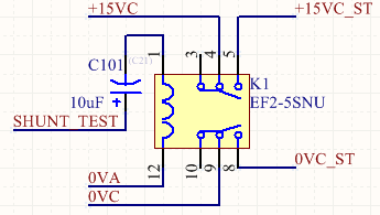
A much simpler solution is to use a capacitor in series with the coil. That way you only need a single output. I use a 10uF cap for the EF2-5SNU (look up the EF2-3SNU datasheet as the 5SNU is out of production).

Setting 5V on the +ve side of the cap causes current to momentarily flow through the discharged cap energizing the coil setting the relay. The Capacitor will charge to full volts. When the +ve side of the cap is then pulled low, the negative side will momentarily be at -5V. This will cause the relay to reset and the cap to discharge. Adjust the cap value to store enough energy for the relay in question.

In this circuit snippet, the buffer drives SHUNT_TEST with respect to 0VA. Disregard the other signals they are part of my circuit being switched.

Keep it simple!

snippet of schematic

\$\endgroup\$

Your Answer

By clicking “Post Your Answer”, you agree to our terms of service and acknowledge you have read our privacy policy.

Not the answer you're looking for? Browse other questions tagged or ask your own question.