1
\$\begingroup\$

I've built a linear power booster - schematic here: http://pedalparts.co.uk/docs/LPB-V3.pdf

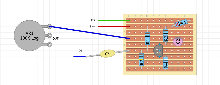
I did it on veroboard:

enter image description here

You'll note that it gives you the option of having different capacitor values to turn the pedal from a 'clean' boost to a treble booster. Ideally I would like to make one with a 3 way switch - ON-ON-ON (double pole) to be able to switch between capacitors.

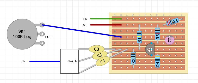
Now I just tried this with a 3 way slide switch that looked like this:

enter image description here

Forgive the crude diagram, but it was a 2 pole switch so I used the other pole to do a similar thing with the other cap (C2, not actually electrolytic, just ceramic)

When I tried it, the first position with the high value (100n) cap sounded ok, but the others were choked and thin sounding. It's a guess, but are the other two (unused) capacitors acting like decoupling caps and filtering out loads of the frequencies? The sound is more trebley, but it's very quiet. Is there a better switching mechanism I could use so that I don't have to have 3 capacitors connected to the same place? Maybe a diode or six?

\$\endgroup\$
6
  • 3
    \$\begingroup\$ We prefer to see real schematic diagrams, rather than pictorials. You should have a ground/common somwhere, where the battery negative terminal and the bottom terminal of the pot are connected. \$\endgroup\$ Commented Oct 5, 2016 at 23:07
  • 1
    \$\begingroup\$ What were the values of the other caps? \$\endgroup\$
    – user207421
    Commented Oct 6, 2016 at 0:39
  • 1
    \$\begingroup\$ \${f_c} = {1 \over {2\pi RC}}\$ \$\endgroup\$ Commented Oct 6, 2016 at 0:53
  • \$\begingroup\$ @PeterBennett, Row I is ground, I just omit ground wires in my pictures. The circuit functions so the grounding is not the issue. \$\endgroup\$
    – TCassa
    Commented Oct 6, 2016 at 10:02
  • \$\begingroup\$ @EJP, the default is 100nF (for both capacitors in the circuit) and the alternates are 10nF and 2.2nF. \$\endgroup\$
    – TCassa
    Commented Oct 6, 2016 at 10:02

1 Answer 1

4
\$\begingroup\$

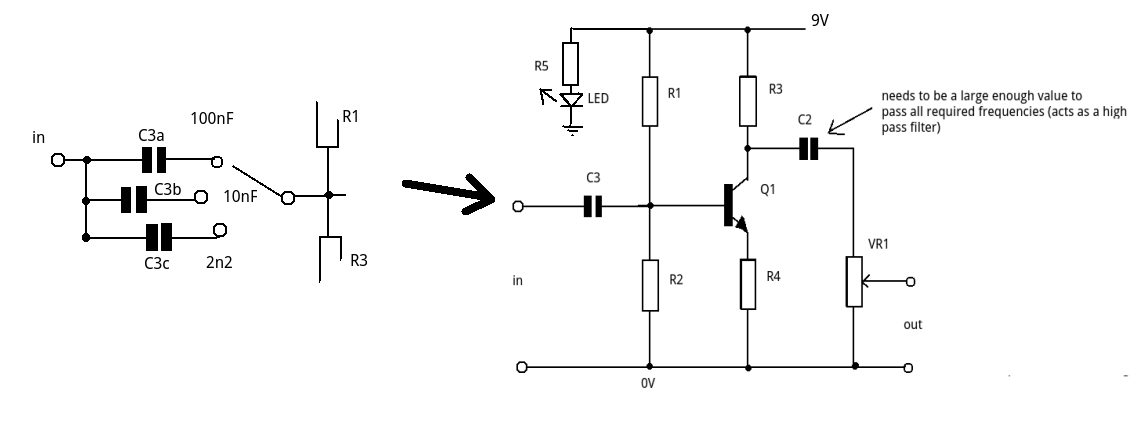
First a schematic diagram rather than pictorial.

enter image description here

This is a very basic single amplifier stage with a voltage gain of approx R3/R4.

Its more of a bass cut than a treble boost (you're cutting out the bass notes) so you lose the bass below the cut off frequency allowing more of the treble to come through.

C3 and R1//R2 form a high pass filter (CR). With C3 = 100nF the sound is OK.

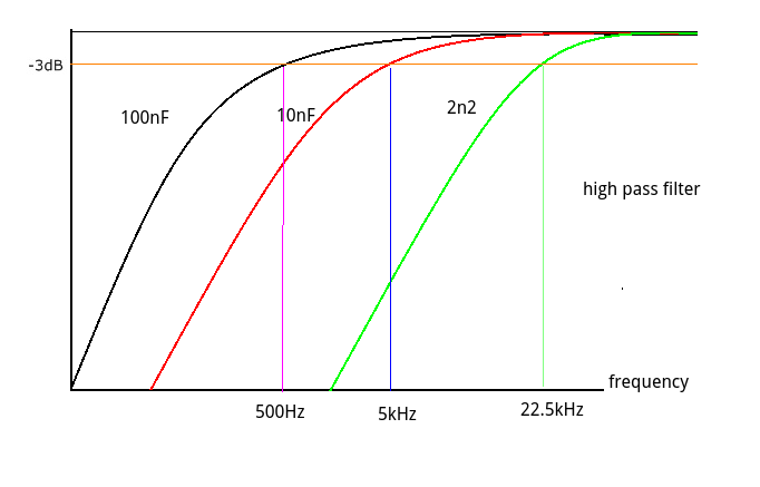
When you switch in the 10nF your are raising the lower cut off by a factor of 10 and the 2n2 by a factor of 45 (ish).

enter image description here

Let's assume that the 100nF gives a lower cut off of 500Hz. Then 10nF gives a cut off of 5kHz and the 2n2 gives about 22.5kHz (i.e. above the threshold of human hearing). Little wonder you can hardly hear anything.

A further complication is the value of C2. If this is too low it also acts as a high pass filter.

Some possible solutions:

(1) Make sure C2 large enough to give a full frequency range output and not acting as a second high pass filter.

(2) Choose values for C3 in a much closer range (2:1). Try a slightly larger value than 100nF as well (say 220nF (more bass), 100nF (clean) and 47nF (trebely))

\$\endgroup\$
3
  • \$\begingroup\$ Don't forget that in this specific amplifier design, there is a very low valued \$R_E\$ that affects the \$R_1\vert\vert R_2\$, significantly (even with a high beta BJT.) Also, little-re will be significant because \$V_E\$ of \$Q_1\$ is close to ground -- I estimate somewhere between \$100\:\textrm{mV}\$ and \$140\:\textrm{mV}\$. So the gain will be responsive to temperature. (Several similar designs I've seen use a bypass cap on \$R_E\$ [high gain depends on \$\beta\$ and even more responsive to temps] and use the pot to pick up the differences.) \$\endgroup\$
    – jonk
    Commented Oct 6, 2016 at 16:57
  • \$\begingroup\$ Many thanks Jim - this is very helpful. But I notice the schematic in the link recommends switching BOTH capacitors, whereas you think I should leave the last one at something high. What would a sensible C2 be? Perhaps 220nF? \$\endgroup\$
    – TCassa
    Commented Oct 6, 2016 at 17:40
  • 1
    \$\begingroup\$ @TCassa 220nF would be more than enough for C2 giving a break frequency (high pass) around 50Hz, you could go to 100nF. \$\endgroup\$ Commented Oct 7, 2016 at 9:27

Your Answer

By clicking “Post Your Answer”, you agree to our terms of service and acknowledge you have read our privacy policy.

Not the answer you're looking for? Browse other questions tagged or ask your own question.