2
\$\begingroup\$

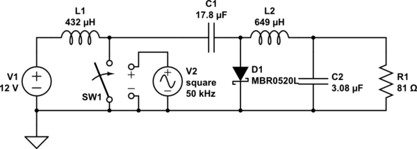
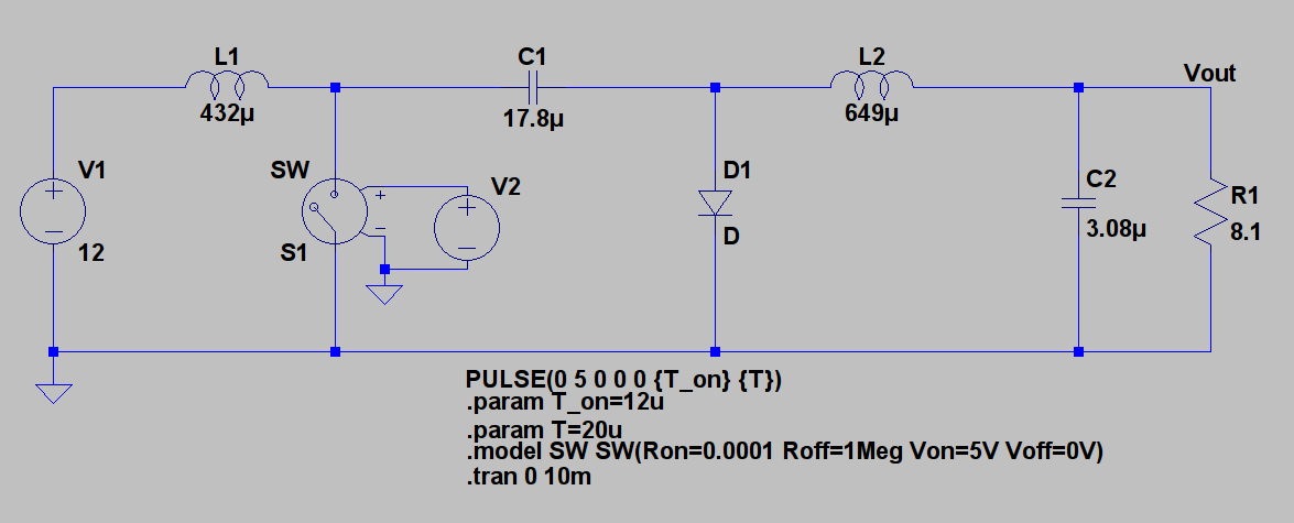
I am trying to simulate an ideal Cuk converter. The circuit parameters are taken from Power Electronics, D.W.Hart, page 230. I set the following circuit:

Cuk converter

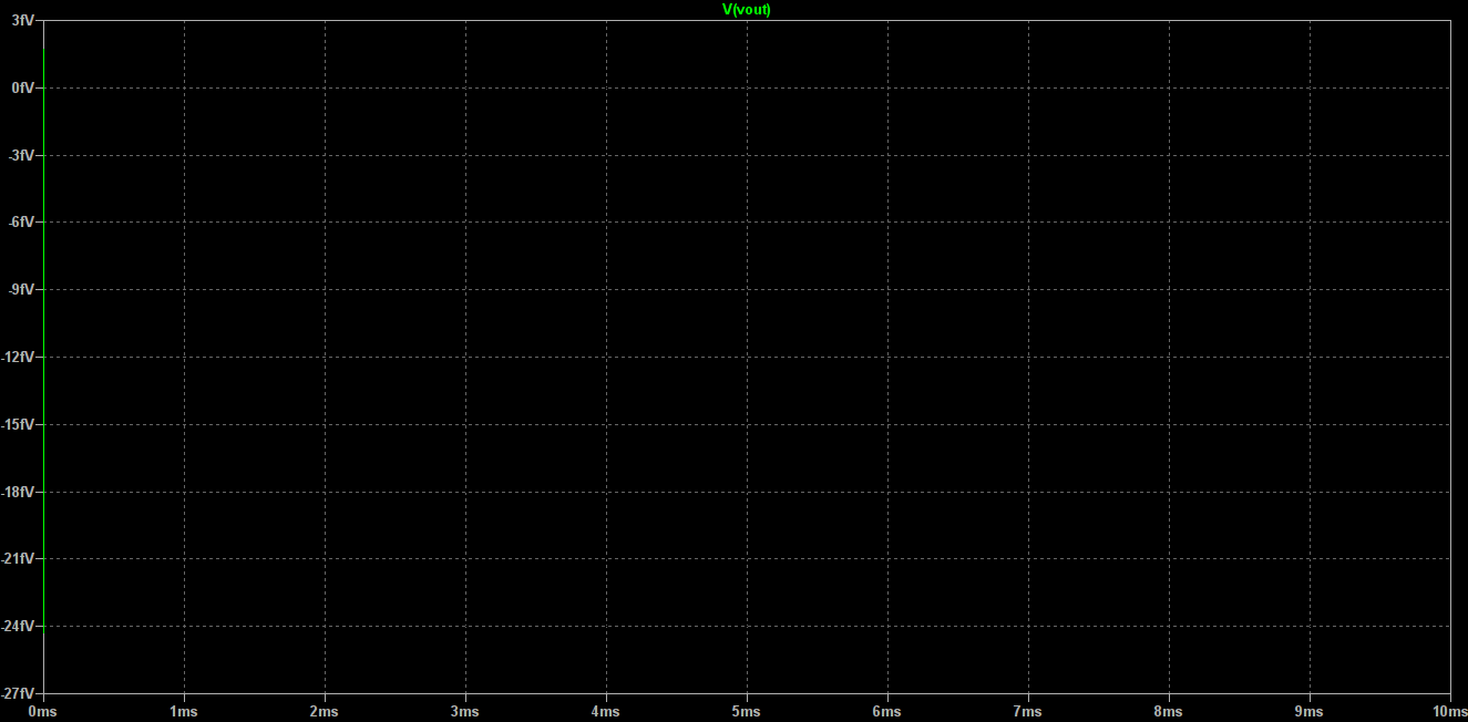
I tried to do a transient analysis. I also tried to change the T_on value and observe the change in output voltage. But the simulation graph shows the following for output voltage:

Vout graph

What's wrong with the simulation?

\$\endgroup\$

2 Answers 2

3
\$\begingroup\$

When using a pulse, you need to specify the rise/fall times, otherwise LTspice will use 10% of the ON time for the zero edges. This will make your Ton larger. This doesn't mean that you should exaggerate by making Trise/Tfall=1p, or similar, you can simply stay within sensible limits. For example: Trise=Tfall=Ton/1000 is a good enough choice. Don't forget that, if you need precise timings, (Trise+Tfall)/2 should be subtracted from Ton. For your case, suppose you need Trise=0.1u and Tfall=0.5u, => Ton=12-(0.1+0.5)/2=11.7u.

For your SW, you're better off using LTspice's native notation, that is Vt and Vh, it makes it much clear where's the threshold and how much hysteresis there is. For your case, and counting the minor example with the timings for the source, above,, it's best to use Vt=2.5 Vh=-2.5. Negative hysteresis means it will not switch abruptly between states, but smoothly, thus reducing the risk of discontinuities ("Time too small" erros & co).

Your diode could also use a more detailed setup. If you want to keep the idealized version, then add this to your schematic: .model d d ron=1m roff=1meg vfwd=0.4 vrev=1k epsilon=50m revepsilon=10m. Or you can simply add .model d d is=1f to make LTspice use the Berkeley SPICE generic model.

Lastly, to improve convergence and make the circuit act more like a quasi-real approximation, you could add Rser=1m to your supply source (this will make LTspice convert it, internally, into a current source, thus improved convergence over voltage sources), you could add some parasitics to your Ls and Cs. For example Rser=10m for C (to limit switching currents, thus keeping values within reasonable limits), and some large-ish Rpar=100k for L (which would add some damping for unwanted oscillations). Note that Rser defaults to 1m for L, if not specified and/or used with coupling.

\$\endgroup\$
3
\$\begingroup\$

I was able to reproduce your problem in CircuitLab. I fixed it by setting the switch threshold to 2.5V instead of 5V. It looks like making the voltage-controlled switch threshold equal to the max input voltage prevents the switch from turning on. You'll probably need to fix the low threshold too.

schematic

simulate this circuit – Schematic created using CircuitLab

\$\endgroup\$
5
  • \$\begingroup\$ I checked your simulation. I agree. When I changed the switch Von to 2.5V instead of 5V, I get the output voltage waveform. However, I get slightly erroneous results. For example, when I put duty cycle to 0.5 (as in your simulation) in LTSpice, the output voltage average on steady state is -15 V. see It should have been -12 V! The situation is the same when I try other duty cycle values. Why does LTSpice behave in this way? \$\endgroup\$ Commented Oct 12, 2016 at 10:13
  • 1
    \$\begingroup\$ Behave this way... opposed to what, calculation or Mr. Hart's results? One thing is that D1 has no model defined for it, so it is using a very basic diode model. I suggest adding real-world components (right-click, choose model) to get a more realistic result. Note that of course LTspice won't model anything particular to an actual physical design, such as PCB trace parasitics. \$\endgroup\$
    – rdtsc
    Commented Oct 12, 2016 at 21:33
  • \$\begingroup\$ @friedrich Check the voltage at the switch node to make sure your duty cycle is correct. If not, have you tried setting Voff to 2.5V as well? Be sure to set valid rise/fall times as mentioned in the other answer. \$\endgroup\$
    – Adam Haun
    Commented Oct 12, 2016 at 22:06
  • \$\begingroup\$ @rdtsc Opposed to the ideal model calculations for Cuk converter. Vout = Vin * (-D/(1-D)). And LTSpice opposes this formula by giving Vout= -15V for D = 0.5 when Vin = 12V. \$\endgroup\$ Commented Oct 13, 2016 at 10:05
  • \$\begingroup\$ @AdamHaun Yes, setting valid times for rise/fall solved it. \$\endgroup\$ Commented Oct 16, 2016 at 7:24

Your Answer

By clicking “Post Your Answer”, you agree to our terms of service and acknowledge you have read our privacy policy.

Not the answer you're looking for? Browse other questions tagged or ask your own question.