1
\$\begingroup\$

I have a setup with a Bender IRDH375 connected to the DC bus of an IGBT based inverter. If I connect a 50kOhm resistor to earth while running the inverter, it detects it well. That part is reasonably ok to understand. However while not running it still detects about 200-400kOhms to ground. How is this possible?

Schematic of setup illustrated below. Only 1 of 3 phases are illustrated for brevety.
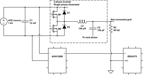
schematic

simulate this circuit – Schematic created using CircuitLab

Shouldn't the IGBT be almost fully blocking while "OFF"?

Update: If I take off R2, the earth meter will show almost maximum insulation (10MOhms). Same if the inverter is running or not.

\$\endgroup\$
3
  • \$\begingroup\$ Does it depend on both AGH unit +/- contacts ? is there leakage in the device or measurement error? What does a DMM say? \$\endgroup\$
    – D.A.S.
    Commented Oct 16, 2016 at 10:07
  • \$\begingroup\$ I can measure a leakage with a live voltage with a DMM? \$\endgroup\$
    – Imbrondir
    Commented Oct 16, 2016 at 13:59
  • 1
    \$\begingroup\$ not safely..if it low Z then arc flash risks exist. I meant compare with "Not running 200-400k values" not AC or DC grid connected. YOu could however put a HiV low W light to hot and measure current ground side as that acts as a shunt. ( e.g. neon tube + string of R's) \$\endgroup\$
    – D.A.S.
    Commented Oct 16, 2016 at 16:44

2 Answers 2

2
\$\begingroup\$

It starts with diagnosing the situation. The dector is very sensitive so you can use the instrument for finding the problem.

  1. Disconnect the incomming DC and inverter connections from the AGH150W and read the effects on the IRD375. If that is wrong then the problem is limited to Bender units.

2.When the first step is ok connect the DC source to the AGH150W and read again. If OK then disconnect the DC source again and connect the inverter and read again.

  1. The last step is to connect both the DC source and the inverter without running and read again.

4 Then run the inverter and read again.

You should be able te find the error by cutting the system in little pieces

From the action taken by OP it has become clear that there is no insulation error but a remaining resistance (not open) between the in and output side of the inverter.

This being the case the only way to make the unit working is to lower the thresholt resistance of the unit just below the measured resistance value. This can be done between 1kOhm and 10MOhm.

\$\endgroup\$
7
  • \$\begingroup\$ 1) DC alone => maximum insulation. 2) DC source alone => maximum insulation. 3) DC source + inverter stopped => 300kOhms. 4) DC source + inverter running => 50kOhms. \$\endgroup\$
    – Imbrondir
    Commented Oct 16, 2016 at 13:52
  • \$\begingroup\$ Also if I take off R2, there is again maximum insulation. Running the inverter or not. \$\endgroup\$
    – Imbrondir
    Commented Oct 16, 2016 at 13:56
  • \$\begingroup\$ If the insulation with is maximum again without R2 then the inverter has 250 kOhms between in and out. There is no other way. Where do D1 and D2 come from? The IGBT has it's own diode inside. \$\endgroup\$
    – Decapod
    Commented Oct 16, 2016 at 14:52
  • 1
    \$\begingroup\$ You have to conclude that the inverter has a resistance between in and out. I looked at the AMP PLUS measuring principle but that does not bring the answer. Since the the insulation resistance with R2 open is ok. You do not have an insulation problem you can adjust the thresholt value of the unit lower and make the system work. \$\endgroup\$
    – Decapod
    Commented Oct 16, 2016 at 15:09
  • \$\begingroup\$ D1 and 2 are the diodes of the igbt modules. I just included them for completeness. Removed the part names that might be confusing \$\endgroup\$
    – Imbrondir
    Commented Oct 16, 2016 at 18:30
1
\$\begingroup\$

If the IGBT is ON or OFF has no relation to the resistance to the earth, since it is all floating. But perhaps it isn't, there are some protective devices like MOVs, or you should start to measure without the connected cable at the output of VFD.

\$\endgroup\$
6
  • \$\begingroup\$ Updated my question specifying that nothing is measured to earth if R2 is taken away. \$\endgroup\$
    – Imbrondir
    Commented Oct 16, 2016 at 13:45
  • \$\begingroup\$ then the freewheel diodes are facilitating completing the path. I am still intrigued why you are surprised there is an earth path when you included an earth path (R2) \$\endgroup\$
    – user16222
    Commented Oct 16, 2016 at 14:25
  • \$\begingroup\$ @JonRB. I do not see the need for the diode D! and D2. The IGBT has the freewheel diodes build in. \$\endgroup\$
    – Decapod
    Commented Oct 16, 2016 at 15:19
  • \$\begingroup\$ Diodes drawn are the built-in freewheeling diodes. \$\endgroup\$
    – Imbrondir
    Commented Oct 16, 2016 at 18:36
  • \$\begingroup\$ Yes the DC bus is floating besides any parasitic conductors to earth. For the diodes to conduct though the DC+ would require a negative voltage to ground. Or a positive voltage on DC-. Maybe that`s exactly it? \$\endgroup\$
    – Imbrondir
    Commented Oct 16, 2016 at 18:42

Your Answer

By clicking “Post Your Answer”, you agree to our terms of service and acknowledge you have read our privacy policy.

Not the answer you're looking for? Browse other questions tagged or ask your own question.