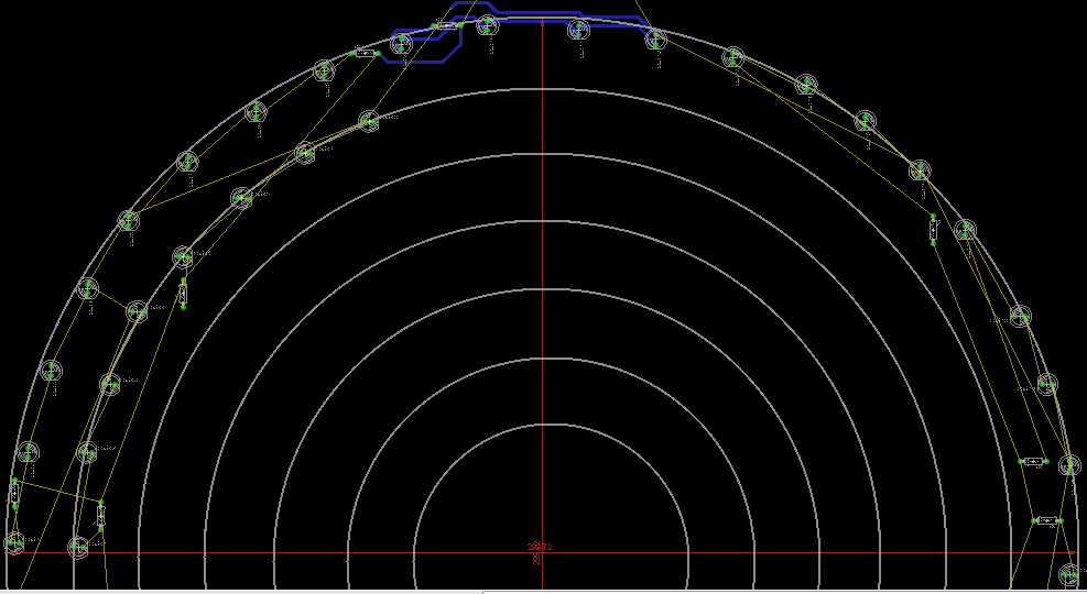
I am designing a blinker circuit in Eagle. These blinkers are used at roadside for indication purpose. These blinkers contain two PCBs. One is PCB contains 555 timer circuit which generate timing. Another PCB contains all the leds. I will be using 12v. I have connected 4 leds in series to make a string and then using 25-26 strings in parallel. I have designed the schematic. But need some help regarding board layout.
As these PCB needs to be in circular shape, so for that I have drawn circles in board layout and planning to put leds on them. Is this the correct way of designing board layout for such kind of PCBs. I also need to put every led at an equal distance to make a proper PCB. Does any one has any experience in designing board layout for these PCBs. Any help or any link would be very useful to me.
Following is the way I am doing it.:
I have drawn circles and putting leds over them. After routing, I will delete the circles and the circuit will be in the proper shape. This is all I can think about designing this circuit. And for the equal distance between leds, I am not using any measuring technique, just putting them with random guess.

