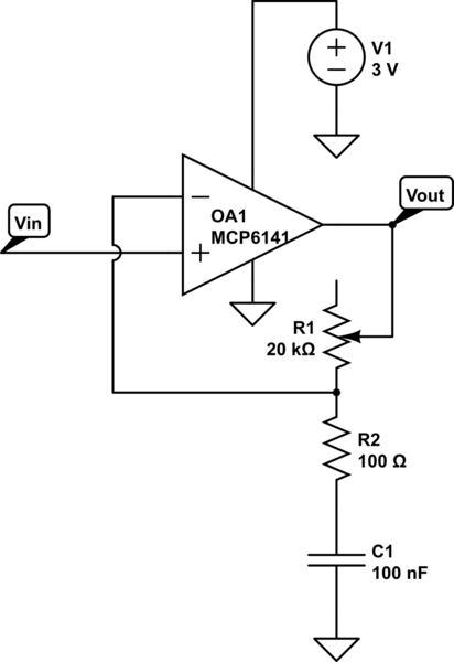
I'm still trying to understand real-life op-amps. I've built this circuit:

simulate this circuit – Schematic created using CircuitLab
Op-amp is an MCP6141 (datasheet) I've chosen for its low-power consumption.
\$V_{\text{in}}\$ is sourced by a waveform generator, and has the following equation:
$$V_{\text{in}} = 1.5\text{ V} + 5\text{ mV} \times \sin(2\pi \times 3.8\text{ kHz} \times t)$$
When \$R_1\$ is between 0 and \$5.9\text{ k}\Omega\$, I have a normal behaviour, signal is amplified, and gain increases. By the way, I obtain a gain of 40 dB for \$R_2 = 5.9\text{ k}\Omega\$, which is strange twice, because
- \$20\log(5900/100) = 35\text{ dB}\$ which is lower than 40 dB
- datasheet says op-amp gain at 3.8kHz is around 30 dB.
As we can see output signal (yellow) is slightly distorted but everything happens as expected (except the gain as explained above).
FTT shows the main frequency is amplified by 40 dB for \$R_1 = 5.9\text{ k}\Omega\$:
But suddenly for \$R_1>5.9\text{ k}\Omega\$, things change and output signal becomes strange:
Does somebody has any idea why there is this strong discontinuity in the regime of the op-amp when \$R_2\$ crosses \$5.9\text{ k}\Omega\$?


