0
\$\begingroup\$

I'm an almost complete newbie to the electrical tinkering circuit so go easy with me please.

My scenario is this: Radio control set up, 2 x 11.1v 5000mah batteries connected in series, runs directly to the Electronic Speed Controller (ESC).

I need to put a switch in-line to cut the power (from source) as and when desired.

I'm going to use a (3-pin) MOSFET with a 1-3v Gate and a max. A throughput rating of 180A, maximum V throughput rating of 40v, however, from the same power source I want to add a 3A switch to activate the gate, so I need a voltage regulator to step down from 22.2v to 3v (all fine I can do that).

However, during usage the Amp draw from the battery may reach 80A! How does that affect my voltage regulator that's spurred off of the same power source? Will it fry it if the AMP draw goes up from the ESC?

What if I added a diode in front of the VR to control the flow of current? Would I need a special diode to be able to stop the Amps flowing to the voltage regulator?

Any help is appreciated, thanks.

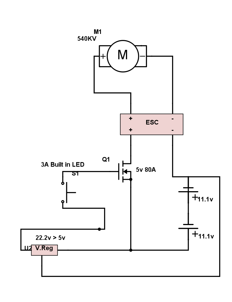
UPDATE: I think this is what I want, but I want to know, would I need one way diodes before the Voltage Regulator to stop the AMP draw messin' with it?

enter image description here

\$\endgroup\$
10
  • 7
    \$\begingroup\$ Draw a circuit of your proposal and identify component names. \$\endgroup\$
    – Andy aka
    Commented Oct 20, 2016 at 12:37
  • \$\begingroup\$ If the voltage regulator is in parallel, it won't be affected. I'm more wondering about whether you're using an N or P mosfet and how you plan to drive it. \$\endgroup\$
    – pjc50
    Commented Oct 20, 2016 at 12:42
  • 1
    \$\begingroup\$ When you say "1-3V Gate" you mean the gate turn-on voltage Vgs(th). You can apply far more than 3V between gate and source with most mosfets, it is usually specified by the Vgss parameter. If this is greater than 22V then you don't need a regulator. If it is less than 22V then you still don't need a regulator, you can use a simple voltage divider consisting of 2 resistors to drop the voltage. I would draw a circuit but I'm not sure if you plan on using an N or P channel mosfet. \$\endgroup\$
    – Steve G
    Commented Oct 20, 2016 at 13:18
  • \$\begingroup\$ Thank you for your replies guys, is there an online facility for me to draw up my circuit please? \$\endgroup\$
    – Kevin Dark
    Commented Oct 20, 2016 at 18:55
  • \$\begingroup\$ @Kevin there is a button on the toolbar of the editor for that. \$\endgroup\$
    – dim
    Commented Oct 20, 2016 at 19:41

1 Answer 1

1
\$\begingroup\$

If you're using a MOSFET for the power switch, then you don't need a "3 amp switch" to drive it, since the MOSFET's gate looks like a capacitor to the driving source. All you need is just enough current to charge up or discharge the gate capacitance in the time desired.

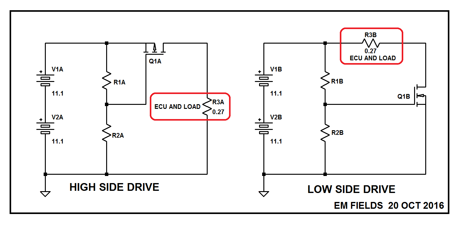
As far as the polarity of the power switch is concerned, you really have only two options, as shown below.

  1. Use a common-source PMOS high-side switch, or
  2. Use a common-source NMOS low side switch.

Of the two, the low side driver is a better choice because NMOS is available with lower \$R_{DS(ON)}\$ which translates to less power lost in the switch and lower temperature operation. For example, an NXP PSMN1R030YLD will dissipate less than 4 watts with 80 amperes through the load.

R1 and R2 represent the RC receiver and the MOSFET driver, so they're shown hot all the time.

enter image description here

\$\endgroup\$

Your Answer

By clicking “Post Your Answer”, you agree to our terms of service and acknowledge you have read our privacy policy.

Not the answer you're looking for? Browse other questions tagged or ask your own question.