0
\$\begingroup\$

I am simulating a discharging capacitor across a changing load. Initially the capacitor is fully charged using a voltage source then it gets disconnected. Next steps
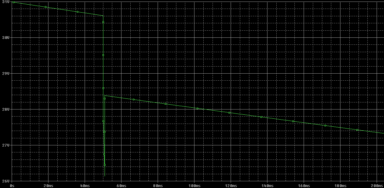
1) A high impedance load is connected to the discharging capacitor say for 50 ms and I can see the voltage decreases slowly 2)After 50ms I connected a lower impedance load parallel to the high impedance load for 1 ms and then I can see a sudden voltage dip (voltage decreases faster) 3)After 51ms I removed the lower impedance load(back to step 1.

After step 3, I should see the voltage should continue decreasing slowly from the point it got decreased(after 51ms) but contradictory to that I see a rise in voltage once I moved to step 3 and then the voltage start decreasing slowly. What is the reason for the rise in the voltage when I changed from lower impedance load to higher impedance load in my simulation.

enter image description here

\$\endgroup\$
6
  • \$\begingroup\$ Useful search terms : ESR, dielectric relaxation. \$\endgroup\$
    – user16324
    Commented Oct 20, 2016 at 17:01
  • 1
    \$\begingroup\$ I would be important to understand what parasitics and non-ideal characteristics are modelled. The effect and magnitude of those should help explain the behavior. (Like @BrianDrummond pointed out.) \$\endgroup\$
    – John D
    Commented Oct 20, 2016 at 17:19
  • \$\begingroup\$ I have included only the ESR of the cap and also the load is resistive. \$\endgroup\$ Commented Oct 20, 2016 at 19:00
  • \$\begingroup\$ Does the ESR times the delta in load current equal the amount of voltage recovery? \$\endgroup\$
    – John D
    Commented Oct 20, 2016 at 19:45
  • \$\begingroup\$ Is there a series inductor as part of the capacitor model? \$\endgroup\$
    – Andy aka
    Commented Oct 20, 2016 at 20:15

1 Answer 1

1
\$\begingroup\$

I think the reason seems easy to see. You observe the capacitor voltage after the ESR, which is always forming a divider network with your varying load. Let's look at the circuit for a moment (I'm sorry you didn't post it as part of your question, so I apologize for any errors I make in interpreting your words here.)
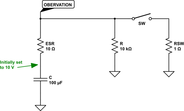
schematic

simulate this circuit – Schematic created using CircuitLab

(The above uses an ideal capacitor and adds the ESR externally for illustration.)

Now, let's run this over a 1 second period and plan on engaging the switch SW at 500 ms, for a period of 1 ms.

From your measurement point, the voltage is at first:

$$V_o = V_C\frac{R}{R+ESR}\approx .999 V_C$$

The voltage, \$V_C\$, declines for the first 500 ms until it reaches about \$6\:\textrm{V}\$, or so, and then suddenly the switch SW is engaged for 1 ms. During this moment, the divider is now:

$$V_o = V_C\frac{R\vert\vert RSW}{R\vert\vert RSW+ESR}\approx .091 V_C$$

In short, a LOT less than before. You only see a portion the voltage on the capacitor for this moment.

Then the switch SW releases and this returns the divider to where it was... But by this time a lot of charge has been removed from the capacitor, too. So it rebounds back a bit. But not entirely all the way, of course.


I've noted where the point of observation is located. I hope you can see why the voltage at this observation point will be very close to \$V_C\$, in the example above, when the switch isn't engaged. Because the current from the capacitor is so low, the \$ESR\$ doesn't drop much voltage and so the measurement point "sees" a voltage that is very close to the actual capacitor voltage at each instant.

However, when the switch becomes engaged, the current from the capacitor increases dramatically because of the suddenly reduced load. As a result of this increased current now flowing also through the \$ESR\$, it drops a much larger voltage than before, causing a larger error in the voltage measurement of \$V_C\$ as seen from the observation point shown. So it is the large drop across the \$ESR\$ that creates that sharp drop in observed voltage. But when the switch is opened again, the capacitor's current returns to a lower value again and this causes a smaller voltage drop across the capacitor and this brings your observation point once again close to the actual voltage on the capacitor.

It just makes sense to me. I hope you can see what is taking place, now.

\$\endgroup\$
2
  • \$\begingroup\$ Thanks for your detailed explanation. Sorry I missed to mention the ESR considered. I am still not clear why the rebound happens because the capacitor is purely a passive element!!!! \$\endgroup\$ Commented Oct 20, 2016 at 21:24
  • \$\begingroup\$ @VenkateshGovindarajan You don't see why? Perhaps you are focused too much on this "passive" idea and not letting yourself see what is going on. The schematic I showed should make it very clear. I'll add a few notes at the bottom that may help. \$\endgroup\$
    – jonk
    Commented Oct 20, 2016 at 21:27

Your Answer

By clicking “Post Your Answer”, you agree to our terms of service and acknowledge you have read our privacy policy.

Not the answer you're looking for? Browse other questions tagged or ask your own question.