2
\$\begingroup\$

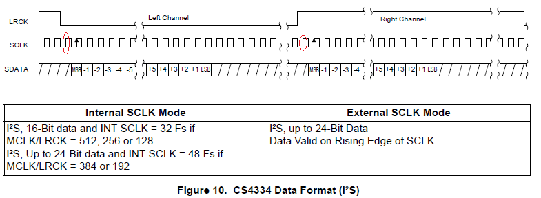
I am getting different waveforms for I2S in different places, in one I found that the LSb is transferred after LRCK has toggled. In this device that is not the case.

It seems that there is normal I2S, left justified I2S and right justified I2S. The left and right justified make sense. However, the normal I2S has something peculiar about it.

Q: Once the LRCK changes polarity, the value of SDATA on the first rising edge of SCLK seems to be ignored. Is this a mistake in the datasheet? Why is this done? The image is below with the questioned part circled red.

enter image description here

Is this a mistake in the datasheet of CS4334? I looked into the "TAS3004 Digital Audio Processor with Codec" data manual page 2-6 and it showed an X for the first bit.

\$\endgroup\$
1
  • 2
    \$\begingroup\$ It's not an "extra clock cycle wasted". It's just a latency of one additional clock period. But it's not wasted, the LSB of the previous sample could be transmitted during this cycle if the number of bits of a data sample was equal to the number of SCLK cycles within a channel period. \$\endgroup\$
    – dim
    Commented Oct 21, 2016 at 8:52

1 Answer 1

4
\$\begingroup\$

Standard I2S does indeed have a one bit offset, I am guessing because in the early days it provided timing to latch the output of the shift register into some sort of parallel input converter (Or maybe the timing for a S/H to get stereo out of a single channel of expensive converter chip or something, yes that was actually done!)..

A lot of this stuff tends to be a case of formalising what is already being done, and 30 odd years later nobody remembers the original reasoning.

\$\endgroup\$
6
  • \$\begingroup\$ I see, by the way why do you think that the sclk clock keeps toggling even after the lsb and not the lrck? I mean the lrck should toggle just after the last bit right? I wonder how does the cs4334 dac know that it had received the last bit in external sclk mode where it says "I2S, upto 24-bit data" \$\endgroup\$
    – quantum231
    Commented Oct 21, 2016 at 8:27
  • \$\begingroup\$ I2S is defined as having 64 SCLK per LRCLK cycle, being as powers of two are easier in hardware dividers then non powers of two, dividing a frequency by 64 is much easier to do in synchronous logic then division by 48... Given that we always have 32 sclks per serial work, it makes sense to (more or less) left justify the input data as that means that providing sign extension is correct, you don't need to care how long the source word is. LRCLK has to run at the sample rate, so the alternative is making SCLK depend on the input word length and nobody wants to go there. \$\endgroup\$
    – Dan Mills
    Commented Oct 21, 2016 at 9:54
  • \$\begingroup\$ I keep coming across variants, I am not sure why we have I2S and then left justified, right justified e.t.c. But anyway... \$\endgroup\$
    – quantum231
    Commented Oct 27, 2016 at 20:53
  • 1
    \$\begingroup\$ Standards are great, there are so many to choose from! \$\endgroup\$
    – Dan Mills
    Commented Oct 27, 2016 at 22:16
  • \$\begingroup\$ By the way, what do you think the -1, -2, -3, .... +3, +2, +1 notiation means? Certainly bits could just be counter as 24, 23, 22 .... 3, 2, 1. Then why these positive and negative numbers? All we need to know is where the LSb and MSb are supposed to be right? \$\endgroup\$
    – quantum231
    Commented Nov 6, 2016 at 13:08

Your Answer

By clicking “Post Your Answer”, you agree to our terms of service and acknowledge you have read our privacy policy.

Not the answer you're looking for? Browse other questions tagged or ask your own question.