0
\$\begingroup\$

PIC18f67j11. For F_OSC which one i have to use: My crystall oscillator frequency or the real frequency oscillator including my PLL modifications?

I'm trying to match the baudRate of the UART and doesn't work. i've tried all reg configurations and baudRate formulas but none of them seems to work.

I'm using a 20MHz external crystall (connected in OSC1 and OSC2) with maximum PLL (OSCTUNE.TUN = 01111) xtal for a 4800bit/s to measure energy by the MCP35F501 meter CI.

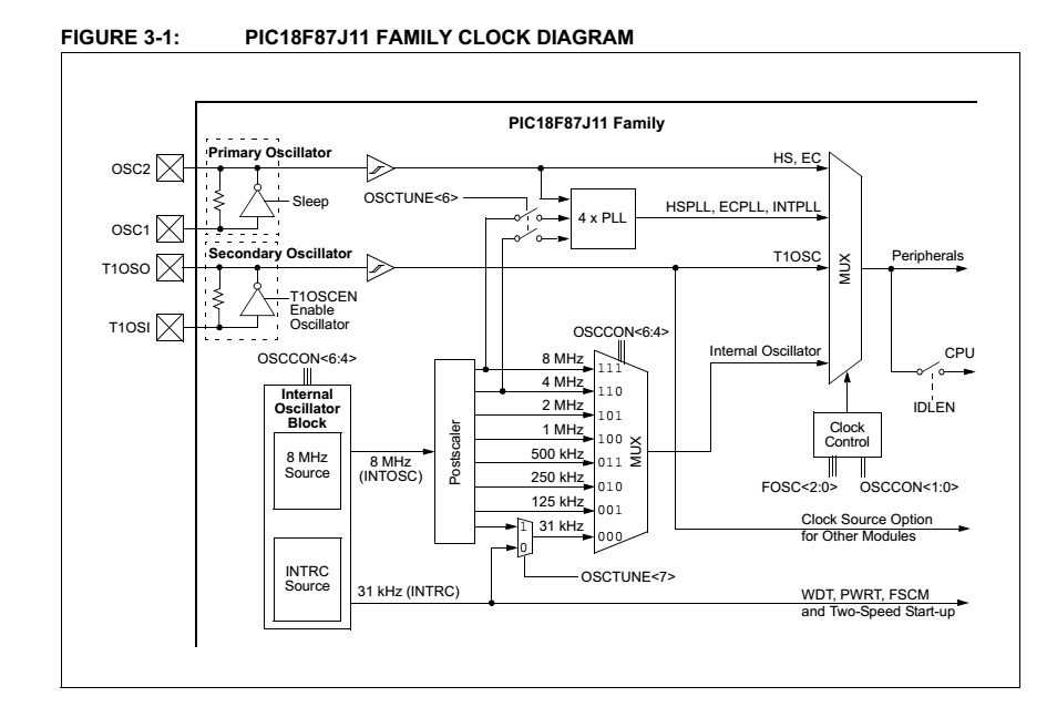
Oscilator Clock Diagram

Here is the clock code selection:

`
#define F_OSC                           20000000 
#define FOSC_PLL                        20000000 * 4  
#define FCY                             F_OSC / 4 
`

`// seleciona clock
    OSCCON  = 0xF0;               // INTOSC = 8MHz; SCS = 00: default primary oscillator
    OSCTUNE = 0b01011111;         // PLL = ON; TUN = 011111: Maximum frequency`

And my UART config:

`
void configureUart(unsigned char uart, unsigned long baudRate) {
` 

    RCSTA2bits.SPEN = 1;
    RCSTA2bits.CREN   = 1;           // Habilita recepção
    TRISGbits.TRISG1 = 0;
    TRISGbits.TRISG2 = 1;
    TXSTA2bits.BRGH = 0;        //Low Speed Mode (baud = 8bits)
    TXSTA2bits.SYNC = 0;        // 0 = Asynchronous Mode
    TXSTA2bits.TX9 = 0;         //Transmissão feita em 8 bits
    RCSTA2bits.RX9 = 0;         //Recepção feita em 8 bit
    BAUDCON2bits.BRG16 = 1;     //16bit Baud Rate Generator 

    TXSTA2bits.TXEN = 1;        // Habilita transmissão
    UART2_RX_INT_EN = 1;        //
    UART2_RX_PRIORITY  = 0;     // Baixa prioridade de interrupção

    baudRate = 1050;//(unsigned long)(FOSC_PLL / (baud_rate * 16)) - 1; TRYING TO MATCH MANUALY TO VALIDATE THE PROTOCOL :#
    // Calcula o novo valor para o registro de configuração do baud-rate
    SPBRGH2 = baudRate >> 8;   // Atualiza BRG da UART1
    SPBRG2 = baudRate;         // ...  
}

`
\$\endgroup\$
10
  • \$\begingroup\$ On way to examine what the baud rate actually is to make a loop that transmits a 0x55 character over and over on the output. With one start bit and one stop bit, this is effectively a square wave of alternating bit times that you can measure with an oscilloscope \$\endgroup\$
    – infixed
    Commented Oct 25, 2016 at 21:13
  • 2
    \$\begingroup\$ I can't see clearly from your description which of the many possible oscillator configurations you are using. You mention a 20MHz, is that an external crystal? If so, you can't use PLL (according to my understanding of the datasheet). Also, the datasheet describes OSCTUNE.TUN as affecting only the internal RC oscillator. Can you show the code with your configuration bit settings, any oscillator register settings, and also confirm whether or not you have an external crystal? \$\endgroup\$ Commented Oct 26, 2016 at 4:38
  • \$\begingroup\$ I'm using a 20MHz external crystall. I've uploaded a pic with the Clock diagram where that seems the Primary oscillator can be multiplied times 4. \$\endgroup\$
    – Henrique
    Commented Oct 26, 2016 at 12:29
  • \$\begingroup\$ See the datasheet page 487 -> PLL Input Frequency Range -> Max 12 Mhz. The part is a 48Mhz (max) part. \$\endgroup\$
    – Tut
    Commented Oct 26, 2016 at 12:47
  • \$\begingroup\$ I make FOSC_PLL = 20MHz x 4 and is working well: baudRate = (FOSC_PLL / (baud_rate * 16)) - 1; //FOSC_PLL = 80MHz. What can happen if i mantain the Pll over the maximum? \$\endgroup\$
    – Henrique
    Commented Oct 26, 2016 at 15:42

1 Answer 1

1
\$\begingroup\$

I'm used the true value of the entrance clock and it's working now. So the value of the FOSC to UART BaudRate calculus is the value of the crystall including the PLL modifications. In resume is the input value of the CPU.

\$\endgroup\$

Your Answer

By clicking “Post Your Answer”, you agree to our terms of service and acknowledge you have read our privacy policy.

Not the answer you're looking for? Browse other questions tagged or ask your own question.