5
\$\begingroup\$

Ignoring the issue of noise, I want to amplify a "static" 0-100mV DC signal to the range of the ATmega328P's 10-bit ADC using a specific voltage reference. Let's assume this reference is 4.096V and call it AREF. This gives me 4mV steps and I need a gain of 40.96.

From what I understand so far, an in-amp such as the AD623 could work for this. It has an input range from 150mV below Vs- (GND in my case) to to 1.5V below the positive rail (which is 3.5V in my case, with a 5V Vcc.) My problem is that the the output voltage range on a single supply has a minimum of 10mV. That means that the ADC will see 0V, 4mV and 8mV all as "0." How can this be avoided?

I can only amplify by about 1.22 times more before hitting the rails on the output, so I don't see how a voltage divider on the output would help...

As far as I know, there's no way to raise the ATmega328P ADC's bottom voltage without doing something like differential ADC, which I read requires calibration that sounds relatively difficult.

\$\endgroup\$
5
  • \$\begingroup\$ Is there a reason that you can not just put 100mv into the AREF pin for the ADC? (28.5.2 in datasheet) \$\endgroup\$ Commented Nov 1, 2016 at 19:28
  • 1
    \$\begingroup\$ I read that the 328p can't use an AREF below 1V. Also, this isn't the only range that I need and while AREF can be switched, I'd rather not. \$\endgroup\$
    – Anthony
    Commented Nov 1, 2016 at 21:00
  • 1
    \$\begingroup\$ Why not add an offset to the input of the amp, which makes the output 10mV when the input signal is 0? You'd lose dynamic range on the signal (because you'd need the output to still over the full 0-100mV swing), but then get away with just using the amplifier. Is there a strong requirement to use the full range of the ADC? \$\endgroup\$
    – iheanyi
    Commented Nov 1, 2016 at 22:56
  • \$\begingroup\$ @iheanyi, at this point that is the much simpler option with much easier to calculate error. I don't have a strong requirement to use the full range. What's the best way to add that offset? I'm having a hard time wrapping my head around it. \$\endgroup\$
    – Anthony
    Commented Nov 1, 2016 at 23:22
  • \$\begingroup\$ @Anthony, I just realized you want to use an in-amp so this may not be an option (because you need to control feedback). Using an op-amp (to build a difference amplifier), you can add an offset to your signal: See en.wikipedia.org/wiki/… Here, you'd connect Rg to the offset rather than ground. To generate the offset, a voltage divider is sufficient. With Rg == Rf, Vout = Voff + (Rf / R1)*(V2 - V1) \$\endgroup\$
    – iheanyi
    Commented Nov 3, 2016 at 20:22

3 Answers 3

8
\$\begingroup\$

When you really need to get to ground on the output so that even a "rail to rail" output isn't good enough, give it negative power. A opamp to drive a A/D input doesn't need much current, so a charge pump should be sufficient.

All you need is a consistently toggling digital output. This can drive a NPN/PNP emitter follower pair. That plus two Schottky diodes and two caps gets you a small negative voltage. Microcontrollers can often drive a pin with a "clock output" or the like, which is useful for making a charge pump from. After the various voltage drops, you only end up with -1.2 V or so when starting with a 3.3 Vpp square wave, but that's plenty to get a many opamps well past their lower rail limit region.

One possible gotcha from this is that the opamp can now drive below the valid A/D input voltage. With the right circuit and making sure the input voltage to the opamp stays within a specified range, you should be able to know the output won't go negative. However, you should consider this carefully.

\$\endgroup\$
3
  • \$\begingroup\$ Olin to the rescue again :) Thanks. After so much reading op-amp data sheets, I really did get curious about negative supplies and didn't know how to create one besides sticking two batteries together and calling the middle ground. \$\endgroup\$
    – Anthony
    Commented Nov 1, 2016 at 12:48
  • 1
    \$\begingroup\$ Something like the LM7705 is useful for creating a small negative voltage supply with minimal components. \$\endgroup\$
    – patstew
    Commented Nov 1, 2016 at 15:32
  • \$\begingroup\$ That looks good but it's not available in DIP. The LMC7660 is similar (more flexible) and available in DIP but more expensive. \$\endgroup\$
    – Anthony
    Commented Nov 1, 2016 at 23:07
7
\$\begingroup\$

If you look at section 28.6.3 of the ATmega328P data sheet you will see that it begins to define the zero offset error that you will get when using the ADC. The upshot of this is that it is extremely sensible not to use (say) the bottom or top 10 mV of the ADCs range because you cannot guarantee that the ADC hasn't hit the "end stops": -

enter image description here

The above picture shows the effect of zero and gain errors and please note that these can be additive as well as subtractive.

So, you have zero error and gain error to contend with and, it reduces your actual numerical range - you have to live with this of course or calibrate each ADC input specifically.

If you look on page 374 it gives you real numbers: -

  • Offset error is quoted as 2 LSBs on a 4V reference and this means the zero may be 0V +/- 7.8 mV.
  • Gain error is also 2 LSBs but you have the added error of the voltage reference not being exactly 4.0960000 volts. Look up the tolerance on that.

In short, use a rail to rail op-amp that is good for getting down to 10 mV and live with the problem like everyone else does.

\$\endgroup\$
4
\$\begingroup\$

First, it is wasteful to use an instrumentation amplifier if the input is ground-referenced, a regular op-amp in non-inverting configuration will work fine (actually better in every way).

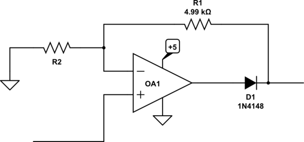
If the op-amp won't go quite to 0V you can put a diode in series with the output as so:

schematic

simulate this circuit – Schematic created using CircuitLab

You could also create a negative supply for the op-amp, but in general that causes additional problems since the op-amp can now swing negative enough to exceed the absolute maximum negative input voltage of the chip. For some MCUs you can stay within the limits by creating a supply that does not exceed -300mV, and there is actually a charge pump chip designed to do just that. There are also band-aid solutions such as adding a series resistor and a Schottky diode to ground, but they can have other issues, and none of them are guaranteed not to cause (perhaps subtle) problems in normal operating even if they don't exceed the absolute maximum voltage or input current specs.

Another possibility that may or may not work, depending on the internals of the in-amp you use would be to raise the reference pin to (say) 20mV and throw away the bottom few counts of the ADC. If an internal node of the in-amp saturates that may not work and there is the additional problem of providing the low-impedance 20mV source for the reference since most in-amps don't have an internal buffer for the reference.


You need to be a bit cautious when working very close to the saturation of the amplifier but not actually driving it to the rail- the characteristics can change quite a bit and micro-instability near the rail can result. Of course you won't find this spelled out in the datasheet and macromodels may not accurately model the behavior.

\$\endgroup\$
4
  • \$\begingroup\$ Thanks. Can you explain why an in-amp is worse in this case? \$\endgroup\$
    – Anthony
    Commented Nov 1, 2016 at 14:15
  • 1
    \$\begingroup\$ The performance (noise, offset etc.) are generally worse for a given cost, or for the best available parts. Choices are fewer and cost is higher. There are more opportunities for internal saturation depending on common mode and supply voltages. Of course if you really need true differential input, then you need it. In some cases you can use a single op-amp as a difference amplifier rather than an in-amp if the impedance to ground is low on the input return line. \$\endgroup\$ Commented Nov 1, 2016 at 14:19
  • \$\begingroup\$ Any recommendations in DIP form? \$\endgroup\$
    – Anthony
    Commented Nov 1, 2016 at 22:39
  • 1
    \$\begingroup\$ DIP is pretty limiting, you might want to consider a low voltage chopper type such as MCP6V71 in sot-23. Vos is well under 1 LSB and it might swing close enough to Vss to avoid the diode. \$\endgroup\$ Commented Nov 2, 2016 at 1:50

Your Answer

By clicking “Post Your Answer”, you agree to our terms of service and acknowledge you have read our privacy policy.

Not the answer you're looking for? Browse other questions tagged or ask your own question.