5
\$\begingroup\$

I'm a bit of a noob, but am trying to manually build an IR receiver circuit from a photo diode and a few other parts (the circuit im trying to reproduce is shown @ http://online.physics.uiuc.edu/courses/phys405/P405_Projects/Fall2005/Nabil_IR_Remote_Control_Demodulation.pdf on page 2).

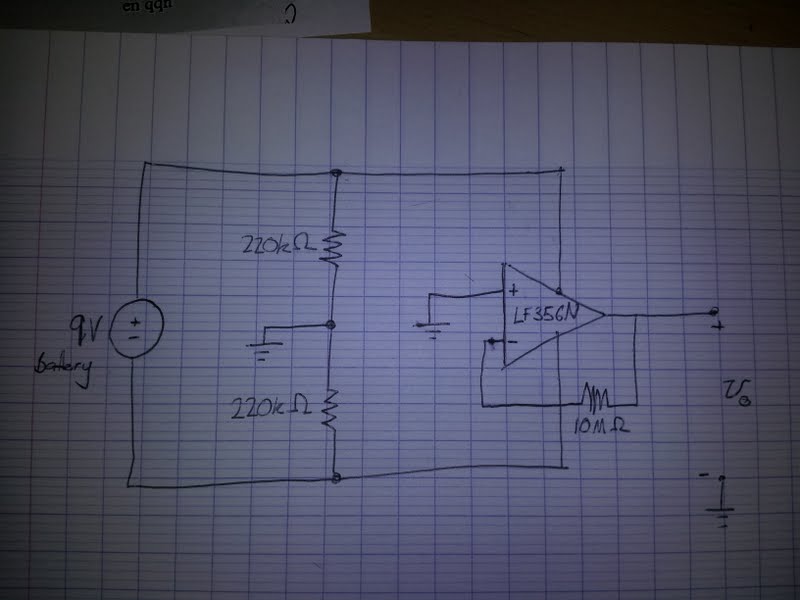
I haven't received all the parts yet, but I figured as I have the op amp and the photo diode I would try just putting the inverting amplifier stage (ie up to point A) together to see if I could see any output from a tv remote on my crappy usb oscilloscope. At some point I noticed a weird 12kHz almost square wave coming from the circuit, even with the photo diode disconnected (circuit diagram shown below).

I was wondering if anyone would be able to shed any light on what's going on? As you can see from the diagram is a very simple circuit, consisting of only a few resistors and an LF356N Op Amp.

Thanks for reading :)

EDIT: It's worth mentioning that I get the same effect with a load resistor across Vo (was using 10M Ohms).
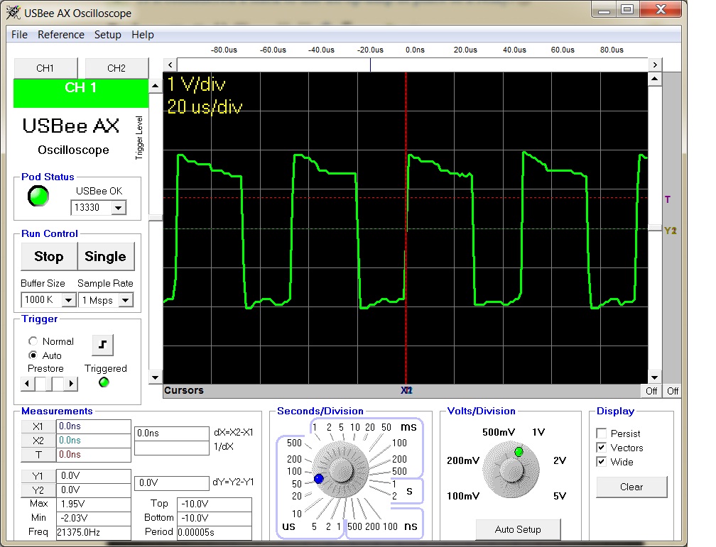
Output waveform

Diagram of circuit generating weird square wave.

\$\endgroup\$
6
  • \$\begingroup\$ You're powered off a 9V, but also show two ground connections. What are they connected to physically? \$\endgroup\$
    – Michael
    Commented Feb 17, 2012 at 3:07
  • \$\begingroup\$ It is just a common node, they're connected to each other. As I said, I'm a noob, but my understanding was the ground just needs to be a common reference point? I use a voltage divider to produce +/- 4.5V for powering the op amp. \$\endgroup\$
    – JBeFat
    Commented Feb 17, 2012 at 3:13
  • 2
    \$\begingroup\$ Your hand drawn circuit is nothing like the circuit you referenced. In your circuit, you have no input to the opamp. Please explain what you're expecting. \$\endgroup\$
    – Michael
    Commented Feb 17, 2012 at 3:13
  • \$\begingroup\$ As shown, your opamp is not getting +- 4.5V rail voltage. its just getting 0 to 9v. \$\endgroup\$
    – Michael
    Commented Feb 17, 2012 at 3:14
  • 2
    \$\begingroup\$ You need to sit down and learn about opamps. There are a lot of misconceptions here, but since you've already accepted a answer they are not worth getting into. \$\endgroup\$ Commented Feb 17, 2012 at 13:17

2 Answers 2

5
\$\begingroup\$

Where's the photo diode (which you expected) and where are the capacitors (which you probably didn't)?

You should be putting capacitors in parallel with the 220K resistors to make sure the ground has a low AC impedance connection to your 9V supply rails. You should be putting a bypass capacitor across the op-amp terminals so that it can source high-frequency currents. You should be putting a small capacitor (10-100pF) in parallel with the 10Mohm resistor to make sure the circuit is stable (this lowers the gain at high frequency).

What kind of circuit construction are you using? If you have a solderless breadboard, it doesn't play well with 10M resistors, and adds lots of undesirable parasitic inductances + capacitances.

\$\endgroup\$
6
  • \$\begingroup\$ The circuit shown doesn't have the photodiode as the oscillation was happening without it. As for the capacitors, I'll give that a try - could the missing small capacitor in series with the 10Mohm resistor be causing the oscillation? I am using a solderless breadboard - should I be using a lower feedback resistance? \$\endgroup\$
    – JBeFat
    Commented Feb 17, 2012 at 3:15
  • \$\begingroup\$ I'd start with a 1M resistor and see how it works; better to use a 2nd stage gain than try to do it all in one stage on a breadboard. Or use perfboard/vectorboard instead; this is a relatively small circuit. \$\endgroup\$
    – Jason S
    Commented Feb 17, 2012 at 3:24
  • \$\begingroup\$ Probably there is parasitic capacitance between the +/- inputs, and the pole (low-pass-filter) caused by that C and the 10M feedback resistor is causing the op-amp output to oscillate. Adding a small capacitor in parallel with it probably will fix your problem. \$\endgroup\$
    – Jason S
    Commented Feb 17, 2012 at 3:26
  • \$\begingroup\$ Would parasitic capacitance be producing such a regular, full swing square wave? That would be strange \$\endgroup\$
    – Michael
    Commented Feb 17, 2012 at 3:29
  • 3
    \$\begingroup\$ @Michael: that's just full-scale oscillations; it's not that surprising. \$\endgroup\$
    – Jason S
    Commented Feb 17, 2012 at 13:32
3
\$\begingroup\$

I had the same problem with a OPAMP circuit.

The problem is that you have a resistance in the feedback path, but almost no current is flowing because it's connected to a high impedence input. So, if a parasitic capacitance appears with the ground or anything else, there is the risk that it starts an oscillation.

What I've done (and you could do), is to remove the feedback resistor as it's useless for that topology.

As Jason said, 12KHz with a 10M resistor means that the capacitance is around 8 fF, that is plausible for a parasitic capacitance.

Edit - it seems to me that the frequency of the oscillation is 21kHz, not 12 (check the box and the time/division); that means a 4~5 fF capacitance, even if it makes no difference.

(As a side note: it took me a Christmas holiday to find out why the Sallen-Key filter I had designed was oscillating)

\$\endgroup\$
4
  • \$\begingroup\$ Thanks for you answer clabacchio. As you and Jason suggested I added a capacitor in parallel with the feedback resistor and it did stop the oscillations. I don't really understand how removing the feedback resistance would help as I though that was needed to get some gain out of the inverting amplifier? \$\endgroup\$
    – JBeFat
    Commented Feb 18, 2012 at 22:27
  • \$\begingroup\$ No it doesn't give any gain, since while no current flows in it, it acts like a short circuit. So, that's why I suggested to just short it. \$\endgroup\$
    – clabacchio
    Commented Feb 18, 2012 at 23:02
  • \$\begingroup\$ So, your Sallen-Key filter was a unity gain one and you have added a big resistor in the feedback path then it was oscillating? What was the frequency of its oscillation and what was the filter's cutoff frequency? I am just curious :) \$\endgroup\$ Commented May 28, 2013 at 8:28
  • \$\begingroup\$ @abdullahkahraman I can't recall it now, but the cutoff frequency wasin the kilohertz, and IIRC the oscillation was in the megahertz... \$\endgroup\$
    – clabacchio
    Commented May 28, 2013 at 17:53

Your Answer

By clicking “Post Your Answer”, you agree to our terms of service and acknowledge you have read our privacy policy.

Not the answer you're looking for? Browse other questions tagged or ask your own question.