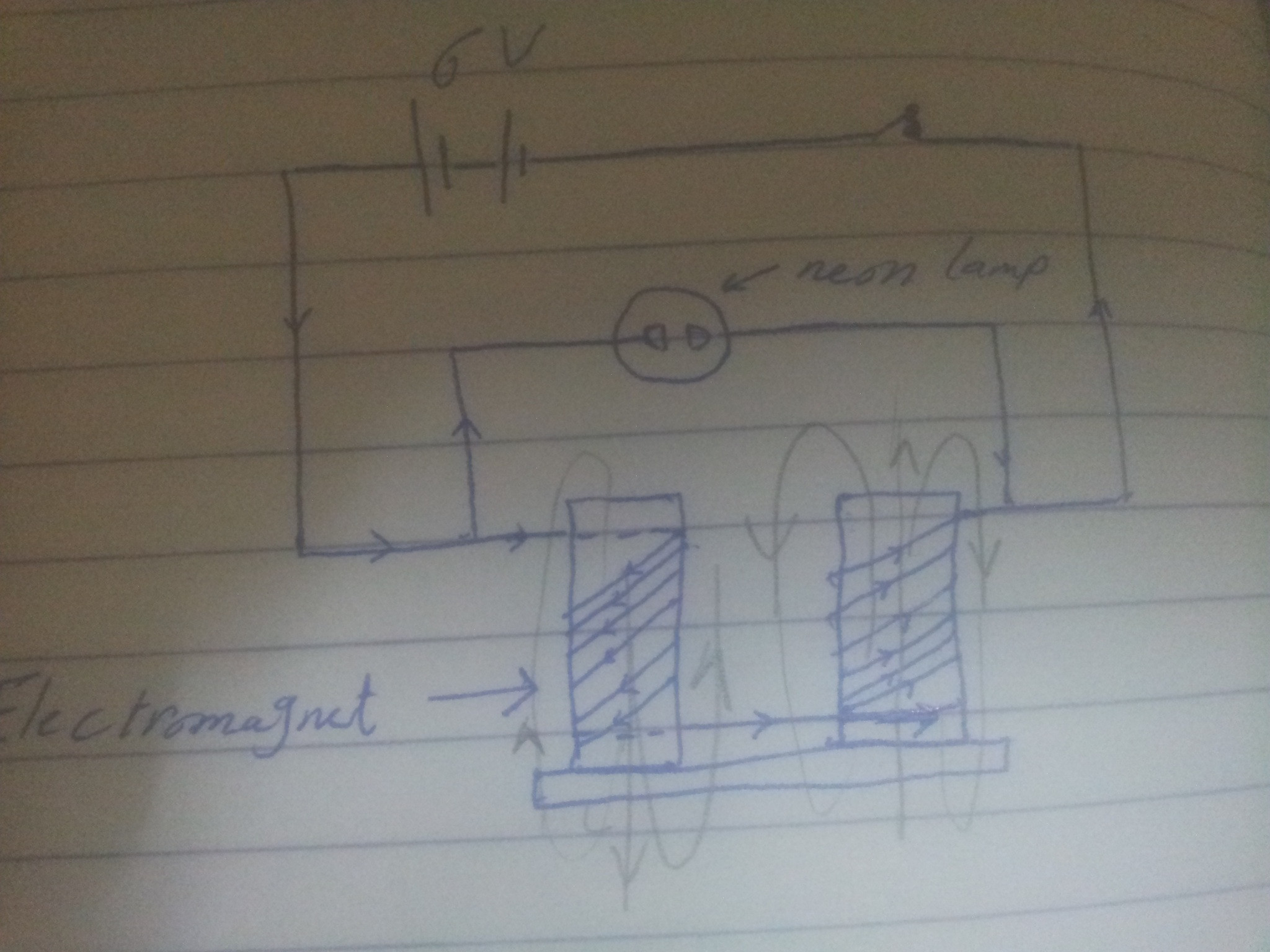
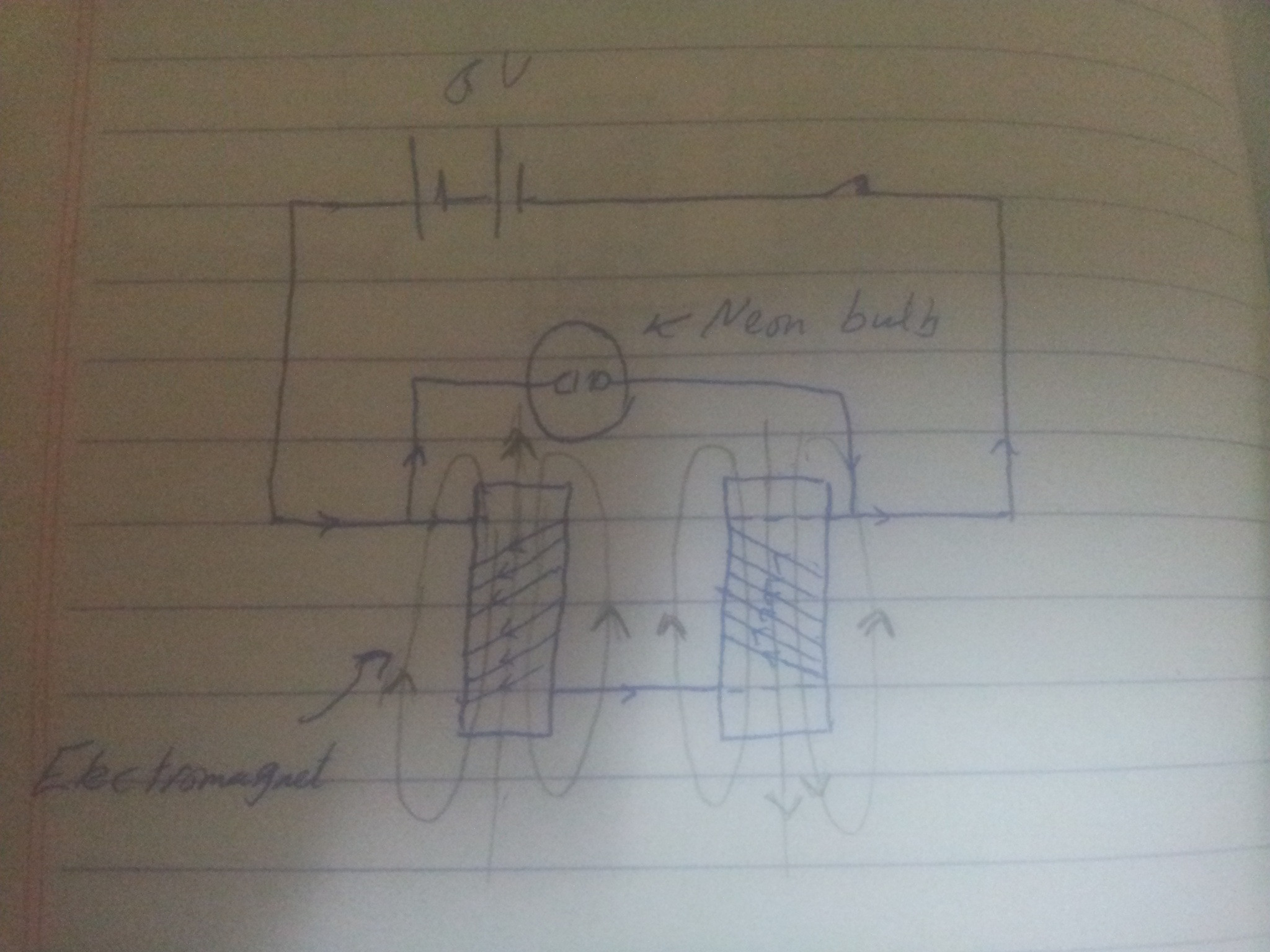
In one article explaining the self conductance a figure like this was used: I added the field lines by myself, what I have noticed in it is the way the two electromagnets are connected by, and I asked myself why they are not connected like this:
 I mean to make the wire coming from the left electromagnet pass behind the core of the right electromagnet, and then the field direction would change. I, to some extent, understand self-inductance, and I wonder if connecting them as in figure 1 is only the right thing to have an induced emf, could you please help me understand the self inductance in this case, and to tell me whether the two connections are right?
Notes: Neon lamp in the circuit is put to prove that a high induced emf will be produced, because that lamp needs 180V, and the battery is only 6V, so the Neon lamp would glow when there is an induced emf.
-
\$\begingroup\$ In the first diagram a horizontal bar is connecting the bottoms of the two electromagnets. What is it, and why is it missing in the second diagram? \$\endgroup\$– Bruce AbbottCommented Nov 7, 2016 at 7:17
-
\$\begingroup\$ Actually that connecting bar is nothing more than a base to the two electromagnets, and I forgot to draw it in the second diagram. And frankly, the book where I see the diagram didn't say anything about that bar, so it wasn't important, and I think I forgot it for that. \$\endgroup\$– AsmaaCommented Nov 7, 2016 at 17:21
1 Answer
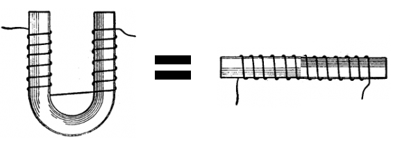
The coils in a 'U' shaped electromagnet are equivalent to a single coil, because they are magnetically coupled via the connecting bar at the bottom. The bar is made of a high permeability ferromagnetic material such as iron or steel. This provides an easy path for the magnetic flux to get from the end of one coil to the start of other, and (combined with the magnetic cores the coils are wound over) reduces the external magnetic field around them.
So even though the external fields in your first drawing are going in different directions and so should be cancelling each other (reducing the total inductance) this effect is swamped by the better flux coupling through the bar. If you imagine bending the bar 180º so the two coils are in line, you will see that the winding continues in the same direction in both coils. As result the total inductance is doubled (compared to two independent coils which are not magnetically coupled) because the flux produced by each coil also goes through the other. This effect is called mutual inductance.
In your second drawing there is no connecting bar, so you simply have two independent electromagnets wired in series. Since these are wound in opposite directions, if placed beside each other their external magnetic fields will add and increase the total inductance - but only by a small amount because each coil's inductance is dominated by its strong internal flux, and the permeability of air is low so external flux coupling is weak and drops off rapidly with distance.

