My device consists of ATMega, GPRS modem and sensors. Modem occasionally hangs and I need to reset it from mcu. The whole system is powered from li-ion battery. I can't find any switching DC-DC converter that would be controlled from the microcontroller, is capable of delivering 3 A current and eats no battery in on-state.
-
\$\begingroup\$ I made some corrections (you should have more care about formulating the question) but what do you mean with the last statement? \$\endgroup\$– clabacchioCommented Feb 20, 2012 at 23:35
-
2\$\begingroup\$ A switching regulator that "eats no battery" is not possible. The best efficiency you'll find for these circuits is in the neighborhood of 95%. To get more help on choosing or designing a regulator circuit, it would help to know what are the input and output voltages you need. \$\endgroup\$– The PhotonCommented Feb 21, 2012 at 0:16
-
1\$\begingroup\$ "eats no battery in..." standby, maybe? \$\endgroup\$– zebonautCommented Feb 21, 2012 at 6:55
1 Answer
The TPS63020 comes close to doing what you want, regardless of what you want :-).
Datasheet here .
Expensiveish at $7 or so in 1's and has charming 3mm x 4mm DSJ package and variants, but is super marvellous.
Buck boost across single LiIon range +.
3A out in most cases.
Variable output version or fixed.
Synchronous input and output switches.
In power save mode it's 60%-70% efficient at 100 uA load meaning if you don't need it it at worst is "wasting" 40 uA compared to your 3A load = 0.0013% power loss. Chance are you can disable it in that mode.
If you can provide a better description of what you want to achieve under what conditions we can provide an even better solution.
Example: Low quiescent current supply idling in background to protect against occasional battery dropout.
I made a SMPS for a product that had 4 C alkaline cells providing 5V (yeah right) and 3V3 rails in an electrically noisy environment. I made a basic boost converter using a 74C14 CMOS gate package as the sole smps controller [!!!] driving two LDO regulators for the electronics. When battery voltage was as high as it should be the LDOs were fed via Schottky's from battery.
If ~= zero drop when on battery had been required a MOSFET could have been used in place of Schottky diodes.*
The smps ran at all times, usually under no load, and When needed the smps seamlessly stepped in to take up the load. Total running standby current including Iq for one LDO was under 100 uA.
These and its various brothers and sisters and many of these .
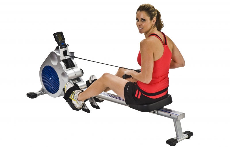
Almost gratuitous picture of one of the products using this arrangement (as far as I know). :

Example 2 : Minimisation of loss when backup protection system is not needed but a "diode" is needed in the battery feed.
* This product uses a forward biased MOSFET for reverse battery protection. The usual battery box terminal style protection was not deemed feasible and a Schottky drops too much voltage when using 3 x NimH cells. When the batteries are correctly inserted the MOSFET is forward biased and is turned on - an inder 20 milliohm Rdson FET is used. When batteries are reversed the MOSFET is reverse biased and never conducts. [MOSFET D & S connections are reversed from usual so FET operates in 2nd quadrant so body diode is reverse biased when batteries are incorrectly connected.
-
\$\begingroup\$ ... must... resist... +1... for photo only... argghhh \$\endgroup\$– tybluCommented Feb 21, 2012 at 15:31
-
\$\begingroup\$ @tyblu - You like the photo of my rowing machine then ? :-). I only did the power supply :-). \$\endgroup\$– Russell McMahon ♦Commented Feb 21, 2012 at 16:38
