I am designing a PCB with Eagle in order to use the LMZ31503 voltage regulator from TI. This IC uses two ground planes, one called AGND and the other one called PGND for power routes. I linked PGND to the GND and am trying to isolate AGND and then somehow linked it at one point to PGND. However, I can't manage to have the two planes isolated from each other when I use polygons with the adequate names followed by the ratsnest function. They fuse together. Is there anyway I can keep them isolated. I have also tried using the ranking and "isolate" properties without significant results. Thank you for your help!
2 Answers
The problem is that eagle does not know which polygon to fill first. For some reason, it doesn't care and "merges" both.
The correct way is this:
- Draw both polygons
- Assign different net names to them
- Assign different ranks to them (e.g. in their properties). Polygons with low rank will now be drawn first.
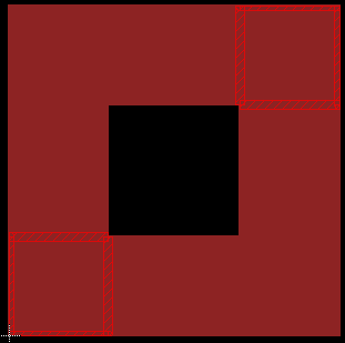
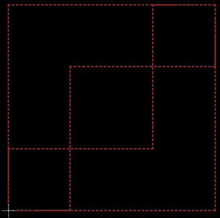
Here is an example with two overlapping L-shaped polygons:
Though different net names are assigned, the polygons are fused. At least, the design rule check will complain:

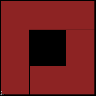
Setting upper left polygon to rank 1, lower right to 2, and applying ratsnest. The upper left polygon is drawn first, the lower left takes what's left:

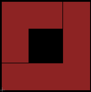
Changing upper lefts rank to 3, the lower right polygon now is drawn first:

I would create a component that is two pads that are physically overlapping. Pin one connects to AGND and pin two connects to PGND thus your netlist is OK providing you draw this component in on the schematic.
You could also add an 0603 zero ohm resistor that connects the two points.
-
\$\begingroup\$ Thank you! And how can I draw the ground planes so that they don't overlap? \$\endgroup\$– Eliott WCommented Nov 16, 2016 at 17:51
-
\$\begingroup\$ Are you able to use a "flood" type command or a copper "pour". I'm not sure what Eagle has in this respect. \$\endgroup\$– Andy akaCommented Nov 16, 2016 at 17:52
-
\$\begingroup\$ Yes, I am currently using the polygon function which is equivalent to a pour. \$\endgroup\$– Eliott WCommented Nov 16, 2016 at 17:57
-
\$\begingroup\$ You call one ground net one name and the other ground net another name and they should not flood into each other. If you have a component seperating them (as I said) they are seperate nets. \$\endgroup\$– Andy akaCommented Nov 16, 2016 at 18:02
-
1\$\begingroup\$ Sorry I can't help you on that because I don't use Eagle. Maybe there is a priority weighting - it's used in OrCAD and PADs to resolve which flood takes priority when they overlap. You might also check what copper-copper clearance figure you have setup. \$\endgroup\$– Andy akaCommented Nov 16, 2016 at 19:03

