0
\$\begingroup\$

I'm trying to create a solution to power an ATtiny85v MCU for maybe two seconds after a power loss to perform some power down tasks, but I don't have much knowledge with electronics. I did some searching but couldn't find an answer to my specific scenario.

The MCU's power is coming from the output of a LDO (Microchip MCP1703T or similar). With my limited knowledge, my idea is to use a capacitor across VCC and GND of the MCU to keep it running for up to two seconds. Powering the MCU with a capacitor has been covered in other questions here, but in my case the capacitor to power the MCU has to be much larger than the specified largest output capacitor of the LDO. Without any components between the MCU's "power off" capacitor and the output capacitor of the LDO, these two capacitors will be parallel connected. Wouldn't that just be the same thing as a single larger capacitor as LDO output capacitor? It would be much larger than the allowed largest output capacitor for the LDO, possibly causing stability issues. How would I go about solving this?

A few notes: I will be doing this on a 17mm board already populated with components for other things and have very limited space. Also, how to detect power loss and how to run the MCU in low power mode is not of interest for this question unless it is of importance to the solution.

\$\endgroup\$
6
  • 1
    \$\begingroup\$ Somewhat related: electronics.stackexchange.com/questions/22157/… \$\endgroup\$ Commented Nov 17, 2016 at 9:21
  • 2
    \$\begingroup\$ You could put the cap before the LDO, instead of after it. \$\endgroup\$
    – Lundin
    Commented Nov 17, 2016 at 9:50
  • 1
    \$\begingroup\$ First things first: Look at the Functional Block Diagram of the LDO. There is a diode pointing backward. This means that if the input voltage falls it may drain your capacitor with it. You may need a diode in the forward direction to prevent that. You could compensate for the voltage drop by adding a diode in the ground connection of the LDO. \$\endgroup\$
    – peter
    Commented Nov 17, 2016 at 13:33
  • \$\begingroup\$ @Lundin: Thanks, I didn't think of that. This would basically mean a very large input capacitor for the LDO, much larger than the specified input cap in the LDO datasheet. Would it be an issue for LDO stabilty? \$\endgroup\$
    – Mike C
    Commented Nov 18, 2016 at 13:51
  • \$\begingroup\$ @Peter: Aha, the LDO might drain it if it's on the output side. I think putting the cap before the LDO is a better idea. \$\endgroup\$
    – Mike C
    Commented Nov 18, 2016 at 13:51

4 Answers 4

1
\$\begingroup\$

Yes, regulator stability could be affected by the added capacitance.

Assuming your required current is relatively low, simply adding a series resistor to the much larger capacitor (or using an electrolytic type with high ESR) should ensure stability without causing too much voltage drop when the added cap is sourcing current.

\$\endgroup\$
1
\$\begingroup\$

I've been doing some testing so I can now add an answer myself for future reference.

I got the best results by putting the cap after the LDO. To prevent reverse current draining the cap during power off I used a LDO that does not let any reverse current through. The one I'm using is the LT1761.

On detected power loss I put the MCU to sleep (sleep mode power down) and set a watchdog timer to wake up the MCU every 120ms to check the voltage with ADC (prescaler division factor 8 to save power), then go back to sleep if the power has not returned. With a 47uF capacitor I was able to measure just over 2 seconds of power off before the capacitor was drained, which is enough for my purposes.

\$\endgroup\$
2
  • \$\begingroup\$ But doesn't putting MCU to sleep change your power requirements? You should reperform this test, but not sleep, keep doing whatever, including the 120ms power check. See what your duration is in that configuration. You want to be able to detect the loss of power, then act on that to save/explode/whatever. \$\endgroup\$
    – lornix
    Commented Dec 25, 2016 at 0:12
  • \$\begingroup\$ The MCU is doing a whole bunch of things that control components that are powered by the same battery that powers the MCU, so when the battery power is gone the MCU has nothing to do anyway. If I don't put it to sleep I can't measure much at all until the cap is drained. \$\endgroup\$
    – Mike C
    Commented Dec 27, 2016 at 9:24
0
\$\begingroup\$

The above answer is a solution, however, if you need to power MCU for 2 seconds after power is cut, you need a big capacitor. Even if the current consumption is very less. You can make a isolated power source which is bypassed when the power is live, but comes into play when the power is cut. (read Schmitt Triggered - Clean Op -Amp Circuit). I could post a working circuit, but i would refrain from doing so.

\$\endgroup\$
0
\$\begingroup\$

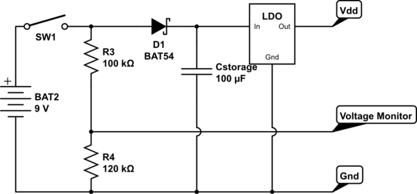
As Lundin says in "comments", the storage capacitor from LDO input to ground keeps the regulator operating - that's the simple solution. Its size will depend on current draw through the regulator. Start by measuring this current with an ammeter between your power source and regulator. Perhaps you know under what condition your microcontroller consumes most current - use this to size the storage capacitance. When your LDO has a higher input voltage (than output voltage), you can get by with a smaller capacitor.

Your more difficult problem is detecting a loss-of-power. To be done before the regulator and the storage capacitor. A logical signal to your microcontroller is required, one logic state says "power good", the other logic state says "pending loss-of-power".
Perhaps you can use one of many power-on-reset (POR) chips to generate "power good". Read this note about the theory of supply start-up. It also discusses power-down detection and the risks involved.
Your battery voltage monitor might be useful for detecting the pending-loss-of-power condition. LDO data sheet specifies a slow start-up time of 1000uS (to prevent output voltage overshoot). It does not specify how output voltage falls, but it is safe to assume that output voltage is always equal to or lower than input voltage. To use voltage monitor as a pending-loss-of-power detector, it will have to be polled often. Possibly a job for the microcontroller watchdog function.
An on-off SPST switch that kills battery power makes the power-loss-pending circuit simple - monitor battery voltage after the switch.

schematic

simulate this circuit – Schematic created using CircuitLab

\$\endgroup\$
4
  • \$\begingroup\$ I am monitoring the battery voltage by feeding + into a voltage divider and then to a pin on the MCU. My idea is to use my already implemented voltage monitoring to detect power off. I don't have any more pins left to use on the MCU, so I really hope I can stick to this. Using a large input capacitor directly on + would also power the voltage divider. I could put a diode between battery + and the "capped" input of the LDO. Would this work? Also, the "power off" cap would be acting as input cap for the LDO, much larger than specified in the LDO datasheet. Would this be an issue? \$\endgroup\$
    – Mike C
    Commented Nov 18, 2016 at 13:43
  • \$\begingroup\$ @MikeC Your diode idea can work. You talk of "power off" - how is this accomplished? A physical switch between battery and LDO? \$\endgroup\$
    – glen_geek
    Commented Nov 18, 2016 at 14:03
  • \$\begingroup\$ Yes, power off is done by a physical switch that turns all battery power off. I'm trying to keep the MCU alive for up to two seconds (maybe one is enough) to detect power off and do a couple of things. \$\endgroup\$
    – Mike C
    Commented Nov 19, 2016 at 7:52
  • \$\begingroup\$ Thanks for the schematic. I've now designed a PCB like this for testing, and also another one with the cap after the LDO. I'll play around with both options. \$\endgroup\$
    – Mike C
    Commented Nov 21, 2016 at 13:41

Your Answer

By clicking “Post Your Answer”, you agree to our terms of service and acknowledge you have read our privacy policy.

Not the answer you're looking for? Browse other questions tagged or ask your own question.