0
\$\begingroup\$

Level: transistor beginner (sorry for that)

Question: is a resistance R1 110 Kohms the good one to put before the b branche of a PN2222 transistor, if we want this transistor being in switching mode when the 0 to 30 volts variable voltage coming into the circuit is above 18 volts, and make the LED lighting above 18 volts ?

Image of the circuit: circuit I put a green led in the circuit
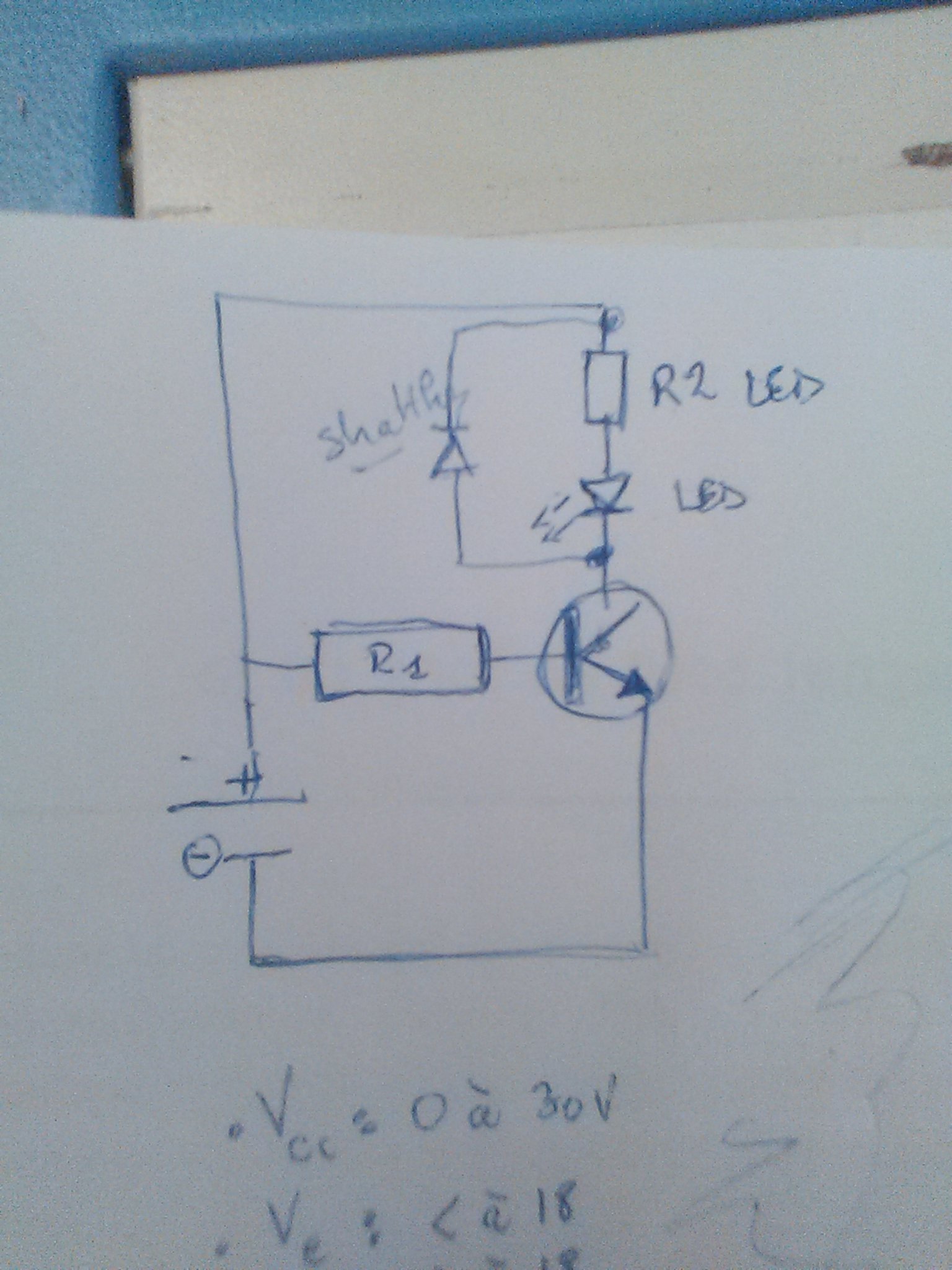
Data: PN2222 transistor data: beta=300; Vce_sat 1=1; Vbe_sat=2; Vce_max=30 LED: Ic=Iled=0,025 A; Uled=2V (green led) R led= 600 ohms (Vcc-Vce_sat-Uled, with Vcc at 18 volts) Source of tension: from 0 to 30 volts Tension where the transistor should light the LED and let the electricity running (contact between c and e): 18 volts

calcul done As: Vcc = Vce + Urel, Vce = Vce_sat, Urel = Rrel x Ic, Vcc = Vce_sat + Rrel x Ic <=> Ic = (Vcc - Vce_sat) / Rrel Then, for Vcc = 18 volts: Ic = (18-1)/600=0,0283 A

And as: Ib_min = Ic / ß Then, for Vcc = 18 volts, and beta = 300, Ib_min = 0,0283 / 300 = 0,000094 A

Lets apply a 1.5 security coefficient to get ib_sat Ib_sat = Ib_min x 1.5 = 0,000094 x 1,5 = 0,00015 A

Then, as: Ve = Ur + Vbe, Vbe = Vbe_sat, Ve = R x Ib_sat + Vbe_sat, so R = (Ve - Vbe_sat) / Ib_sat which gives for Vcc = 18 volts: R = (18 – 2 ) / 0,00015 = 110212 Ohms

Is it the correct value for R to light the LED when the variable tension reach 18 volts ?

\$\endgroup\$
2
  • \$\begingroup\$ Your LED will start to turn on as soon as your input voltage reaches 0.7 V and gradually increase from there. You need a zener diode arangement to achive your undervoltage lockout. A simple 17 V zerner diode in series with the base of your transsitor should solve that. R1 needs to be of much lower value than 110k. \$\endgroup\$
    – winny
    Commented Nov 18, 2016 at 11:15
  • \$\begingroup\$ With new calcul, R1 seems to fall between 28 and 90K. Hower, it does not really sounds great when I put the data into online simulators ... \$\endgroup\$
    – Anc
    Commented Nov 18, 2016 at 14:22

2 Answers 2

1
\$\begingroup\$

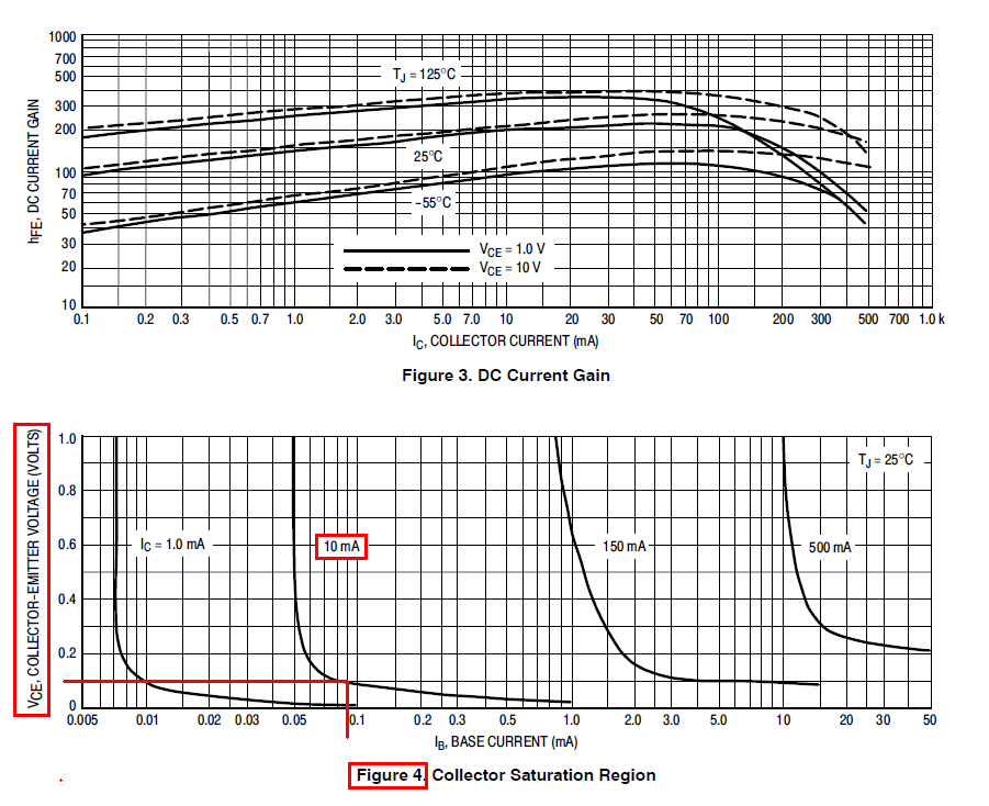
If you look at the data sheet of the PN2222 you will see that the hFE of the device is much lower than 300 for saturation mode. For instance with 10 mA flowing and a quite large 10 volts across collector and emitter, hFE has dropped to a minimum value of 75 and, I think it's reasonable to assume that hFE is less when operating the transistor in saturation.

Figure 4 gives some more detail for typical values (not guaranteed): -

enter image description here

For 10 mA collector current and a saturation voltage of 100 mV the base current might typically be 0.09 mA implying a hFE of 111 but, remember this is a typical value so I would probably assume hFE might be as low as 30.

You can also see that hFE varies quite a lot with temperature (figure 3) so assuming a hFE of 30 is probably not unreasonable in certain situations.

The trouble with your requirements is that relying on a fixed value of hFE is going to disappoint you. This is because you have drawn a fairly linear circuit and I would be tempted to put a zener diode in series with the base resistor that basically blocks significant amounts of base current until the supply exceeded 18 volts.

\$\endgroup\$
4
  • \$\begingroup\$ Putting a 17 volts zener diode, and a maximum of 30 to 100 beta value, modify the theorical results. However, I do not know if my calcul are correct ... \$\endgroup\$
    – Anc
    Commented Nov 18, 2016 at 14:24
  • \$\begingroup\$ You have the zener diode shown the wrong way round - it needs to block a positive voltage until about 17 volts is reached. You can also add series zeners to give a composite blocking voltage. I'd also put a 10k resistor from base to emitter. Why don't you download (free) LTSpice and let it do the hard work - no need the breadboard etc.. \$\endgroup\$
    – Andy aka
    Commented Nov 18, 2016 at 14:34
  • \$\begingroup\$ Thank you for the way the zener diode should be placed. I will turn it in the opposite way. Great. Adding others diodes and a 10k resistor, sounds also great; But I have to understand how I could do that (sorry to be so beginner). The LTSpice software seems not working for my OS ... \$\endgroup\$
    – Anc
    Commented Nov 22, 2016 at 20:02
  • \$\begingroup\$ I don't think I can help you fix the LTSpice problem but good luck. \$\endgroup\$
    – Andy aka
    Commented Nov 22, 2016 at 21:29
0
\$\begingroup\$

Then, if I include a Zener diode, into the circuit, that might give this:enter image description here

With following values:

  • R.led: 1500 ohms, where R.led = (V.e – V.ce-sat – U.led) / I.led
  • I.led: 10mA
  • U.led: 2V
  • DZ:17V
  • PN2222 Beta: between 30 and 100
  • Vin: between 0 and 30 V
  • Ve (switch voltage value targeted): 18V

Then, if I re-calculate the value of R with a Beta lower than the maximal value given by the datasheet, and more aligned with proable reality:

  • with Beta = 100, then my calcul gives R = 95.000 ohms
  • with Beta = 30, then my calcul gives R = 28.000 ohms

Equations and calculs (here Beta=30):

  • I.c = (V.cc – V.ce-sat) / R.led = 0.0113 A
  • I.b-min = I.c / Beta = 0.00038 A
  • I.b-sat = I.b-min x 1.5 = 0.00057 A
  • R = (V.e – V.be-sat) / I.b-sat = 28.235 Ohms
\$\endgroup\$
3
  • \$\begingroup\$ Your zener is reversed, otherwise it's much better! Now you need to saturate the transistor with base current while surviving power dissipation and not exceed any maximum rating if you want Rled to determine your LED current. \$\endgroup\$
    – winny
    Commented Nov 18, 2016 at 14:32
  • \$\begingroup\$ Your calculation for the base resistor is just wrong. It should be much higher. Say you use a 16V zener and aim for it to be fully on at 18V and start turning on nominally at 15.4V, then the resistor would be 1.4V/.38mA = 3.6K. Then the maximum base current is 3.7mA, not ~500mA which will burn out the transistor and zener. Also add a resistor (I suggest 10K or so) between base and emitter because the zener still conducts a bit below its nominal voltage. And flip the zener. \$\endgroup\$ Commented Nov 18, 2016 at 15:47
  • \$\begingroup\$ thank you winny and spehro. I see calculs I did seem wrong. For what I understand, the resistor should be (Vzener-Vzener-start-nominally)/I.b-min. If so, as a beginner, I'm trying to understand the result you give for the 3.7mA maximum base current ... but I've not succeed in. \$\endgroup\$
    – Anc
    Commented Nov 22, 2016 at 20:26

Your Answer

By clicking “Post Your Answer”, you agree to our terms of service and acknowledge you have read our privacy policy.

Not the answer you're looking for? Browse other questions tagged or ask your own question.