1
\$\begingroup\$

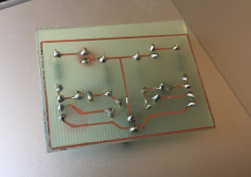
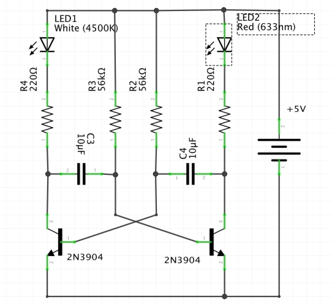
I am pretty new with this stuff, just learning. I wanted to make a simple PCB, and as this was my first project, I decided to go with astable multivibrator circuit, to oscillate 2 LED's using transistors and capacitors. Unfortunately when built (and sadly I didn't bother to breadboard this first for some reason) only one of LED's (white) was lighting up and just staying like that. Because I am new to this, I am not sure how to approach the concept of "troubleshooting" and debugging the problem. So any advice is appreciated. I am attaching schematic, PCB, and the photos, with some data to make things clearer.

Several places I might have got this wrong are - maybe wrong resistor values? if so what are the correct ones? Also I think I am not seing a difference between 10nF and 10mF (the myu letter for m) maybe I put wrong capacitors in? Maybe wrong transistor? I just had this one. Lastly ignore the LED values on the schematic, I just used some led's I had at home, and there is no values written on them, so I don't know. It's just regular LED I suppose.

Thanks!

Update 1: it appears I had wrong resistors for collectors, I had 2.2k instead of 220, so that is fixed now, and white led is brighter. Oscilation still not happening.

Update 2: It also appears I had polarity of capacitors wrong, that is fixed with no effect.

Update 3: Tried some messing around, like shortening transistor CE on the red led side. This causes a short blink (white off, red on) then in a milisecond white comes back, and red still remains (so both on). if shortening is removed, red turns off, and white remains. Not sure if this can hint a problem or not.

Update 4 As it was suggested apparently I got the C and E of transistor swapped somehow o_O. So got this fixed. Blinked for a second, and red was much deemer then the white.

Update 5 Changed LED's to both be the same green, as well as changed Capacitors to 100uF, and base resistors to 4.7k. (As it was suggested by many my current resistance for base was too high, and capacitor change was to keep same frequency of oscilation. Didn't work as well.

Update 6 After examining each part of board, I found a small part that was not connected. Self made PCB's are not reliable as someone from comments suggested :) This did make thing finally work, nice and steady green blinking led's. Yay!

At the end funny thing is that EVERYTHING was wrong with this board. and Everyone who commented had found something important :D Thanks! I hope I get better at this, currently I beter retreat into my embarassement cave.

enter image description here enter image description here enter image description here enter image description here

\$\endgroup\$
11
  • \$\begingroup\$ Looks like both capacitors are soldered the other way round, with wrong polarity. Also base resistors seems to be rather high value: I'd try with some much lower (around 5kohm) and caps around 100uF then, for same blink rate. And what about LEDs polarity, I cannot see, just try to individually short transistor CE, its own LED should light. \$\endgroup\$
    – carloc
    Commented Nov 20, 2016 at 17:04
  • \$\begingroup\$ The LED polarity is fine I tried powering them directly on the board. (Basically the flat part of led is facing up) as for capacitors, I did not know they had polarity O_O oups.... is there any way to figure out now that it was soldered? \$\endgroup\$ Commented Nov 20, 2016 at 17:48
  • \$\begingroup\$ oh yes can you see the white stripe with minus minus minus... printed? Those should be connected to transistor base \$\endgroup\$
    – carloc
    Commented Nov 20, 2016 at 18:10
  • \$\begingroup\$ okay so if I understand correctly, the "long" wire of capacitor is the +, and + of capacitors should be facing outwards in this schematic, so that "-" goes to bases of transistors. (short pins that is) So, I just resoldered that, with no effect :( (just white LED lights up) I have also fixed the 220 resistors (as I used 2.2k by mistake) so this are fixed as well.. The only thing left is the base resistors being too high? can this cause this problem? should I change them? \$\endgroup\$ Commented Nov 20, 2016 at 18:13
  • \$\begingroup\$ Part of your problem may be that the LEDs are different VF's. The white LED is about 3.2 V and the red LED likely 2.1-2.2 V. \$\endgroup\$ Commented Nov 20, 2016 at 18:26

2 Answers 2

3
\$\begingroup\$

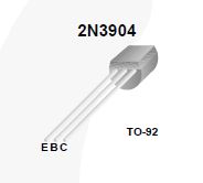
It look like you have your collector connect to ground. The 2n3904 Transistor pinout looks like this;

2n3904 pinout

\$\endgroup\$
4
  • \$\begingroup\$ This. Flip the transistors (E and C are swapped). The transistors will "sort of" work in this configuration with a 5V supply, but their gain will be so low that the circuit will likely not oscillate. \$\endgroup\$ Commented Nov 21, 2016 at 1:01
  • \$\begingroup\$ hmmmm, okay this could be it, I'll re-try today, and report back here! Thanks! \$\endgroup\$ Commented Nov 21, 2016 at 13:48
  • \$\begingroup\$ This was it! (alongside with bunch of other stuff) Thanks \$\endgroup\$ Commented Nov 21, 2016 at 15:37
  • \$\begingroup\$ It's pretty hard to decide, because everyone here helped, and all of the voiced issues were there. But I guess the transistor screw up was the major one. Accepted this one. But really - thanks to everyone. \$\endgroup\$ Commented Nov 21, 2016 at 16:39
1
\$\begingroup\$

The collector resistors look like they are 11K rather than 220R. This will stop the LEDs illuminating.

\$\endgroup\$
6
  • \$\begingroup\$ Maybe the colors on photo aren't right, but That's Red Red "Black" Brown Brown which should be 2 2 *10 with 1% accuracy. if I am correct. This somehow have 5 colors instead of 4, so I ignore the black in the middle. does it make it 22k ? The white LED does illuminate (not very bright though), and red does not. But it's not like white flashes. white is always on. \$\endgroup\$ Commented Nov 20, 2016 at 17:16
  • \$\begingroup\$ It's 2200Ω then. You must not leave out rings. \$\endgroup\$
    – Janka
    Commented Nov 20, 2016 at 17:20
  • \$\begingroup\$ oh :( so how does 220Ω look in this "five" ring format then? \$\endgroup\$ Commented Nov 20, 2016 at 17:29
  • \$\begingroup\$ must be red red black black brown. let me resolder. thanks! \$\endgroup\$ Commented Nov 20, 2016 at 17:46
  • \$\begingroup\$ fixed the resistors issue, white LED is now much brighter :) Although it did not fix the main problem, as white LED is on all the time. \$\endgroup\$ Commented Nov 20, 2016 at 18:15

Your Answer

By clicking “Post Your Answer”, you agree to our terms of service and acknowledge you have read our privacy policy.

Not the answer you're looking for? Browse other questions tagged or ask your own question.