1
\$\begingroup\$

I seem to be having issues getting my new PCB etching setup to work.

My earlier setup worked just fine which included:

  1. printing negative artwork on a parchment paper
  2. exposing a copper pcb with negative photoresist film on it through this negative under a regular table lamp
  3. treating this with Sodium Carbonate, Ferric Chloride and finally with Sodium Hydroxide (in order)

This produced acceptable results (I was able to go down to 10 mil trace width). However it took a long time as I was exposing with a regular table lamp (around 50 mins per side).

So to get more consistent and finer results, and to speed up the process, I decided to make the following changes:

  1. use laminator to attach the negative photo resist film to the pcb instead of using a hot iron
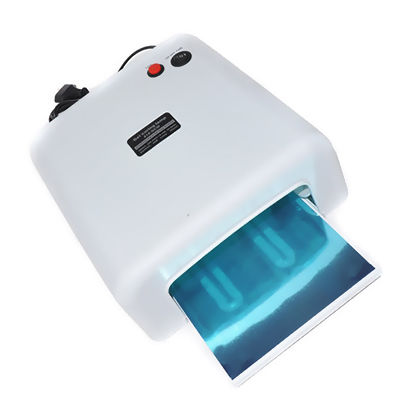
  2. use an UV lamp for exposure enter image description here
  3. used 2mm transparent acrylic sheet to sandwich the pcb between the artwork (instead of glass). Mainly because I broke the glass and had acrylic sheet lying around

Needless to say, the new method did not work as I expected. The issues that cropped up:

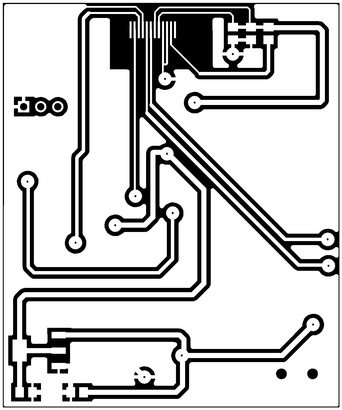
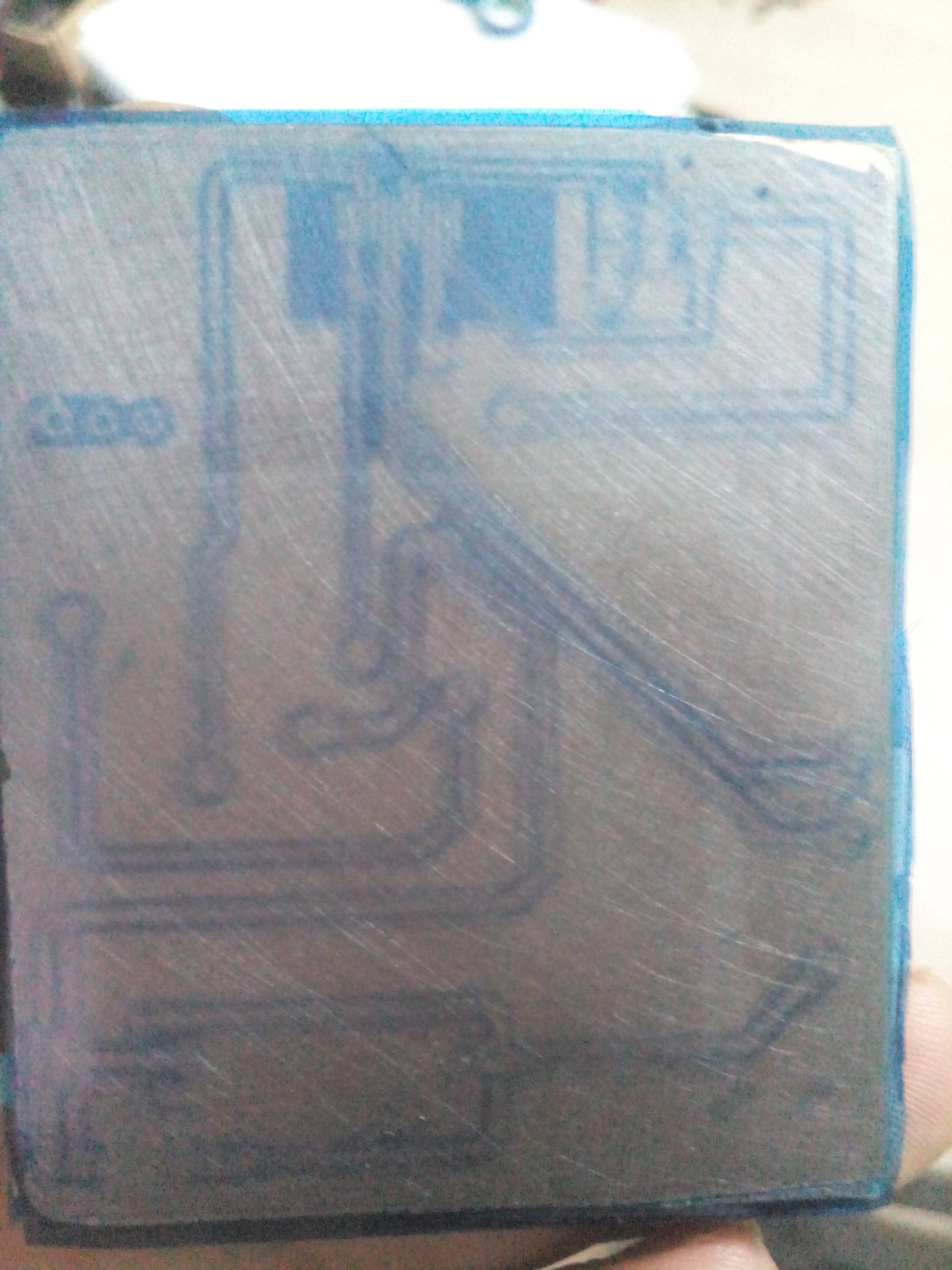
  1. The pcb after exposure seems underdeveloped. The white areas in the artwork (where copper should not be etched away) should be dark blue after exposure. However as seen, that is not the case. They seem to have virtually no change in color at all. enter image description here enter image description here

  2. The tracks are fuzzy. I think that's because of acrylic sheet bending on the edges when clamped. So that's not a big deal. Can be solved by using glass. (there is a prominent displacement of tracks in the picture because I took the pcb midway and then exposed it again without thus causing misalignment)

If I go ahead and rinse this is a solution of Sodium Carbonate, I don't see unexposed photoresist (under the black area of the artwork rinse off), again pointing to under development as the cause.

I am not sure what could be the issue here. Is it because the acrylic sheet is blocking uv rays thus causing pcbnot to be developed properly or is my uv unit to too weak. I has 4 bulbs, each 9W enter image description here

Would appreciate any guidance here.

Update:

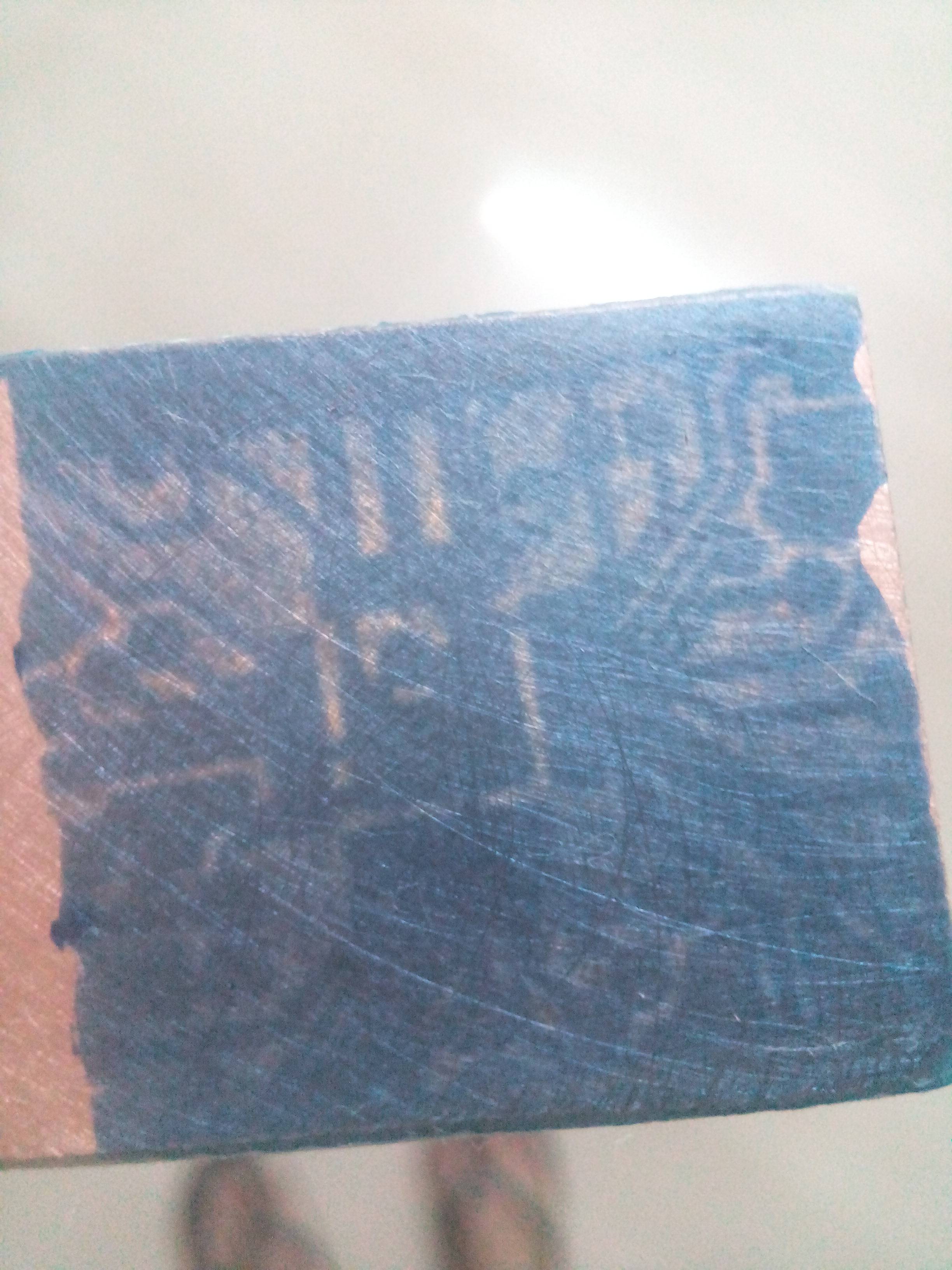
Picture of result using a drop of oil to hold the artwork and skipping the acrylic sheets

enter image description here

\$\endgroup\$
9
  • \$\begingroup\$ Are you sure the UV exposure time is really adequate and that the acrylic doesn't act as a UV filter? \$\endgroup\$
    – PlasmaHH
    Commented Nov 28, 2016 at 9:51
  • \$\begingroup\$ And are you sure that the bulbs are really UV? You often get "UV effect" lighting sold that's barely in the UV range, just enough to make your clothes light up weirdly, but mostly in the violet visible spectrum. \$\endgroup\$
    – Polynomial
    Commented Nov 28, 2016 at 9:53
  • \$\begingroup\$ Nope. I am really not sure if the bulbs are UV since I don't have access to an UV meter. They do have UV printed on them and yes they do produce "violet" light. Got them from aliexpress so yes, they could be fake. For the acrylic filtering out the UV light, I did do a google search but could not find any conclusive answer as it depends on the composition of the acrylic. I was hoping someone had faced this before so could tell what it could be exactly, crappy UV or the acrylic. Assuming the UV bulbs are genuine, is 9W in general enough for PCB exposure? \$\endgroup\$
    – Ankit
    Commented Nov 28, 2016 at 10:15
  • \$\begingroup\$ Have you tried exposing in the sun than an UV lamp? I know it sounds very low tech but that seems to work with normal glass plates. Exposure time is about 5 mins. \$\endgroup\$ Commented Dec 1, 2016 at 6:59
  • \$\begingroup\$ Also make sure the dry photoresist films that you are using are applied in a semi dark room or one that's illuminated by LED lights and not fluorescent or candescent bulbs. The film itself turns dark dark blue when exposed to UV. Why are you using parchment paper to transfer the layout to the board? Why not use transparencies or clear films? \$\endgroup\$ Commented Dec 1, 2016 at 7:52

2 Answers 2

1
\$\begingroup\$

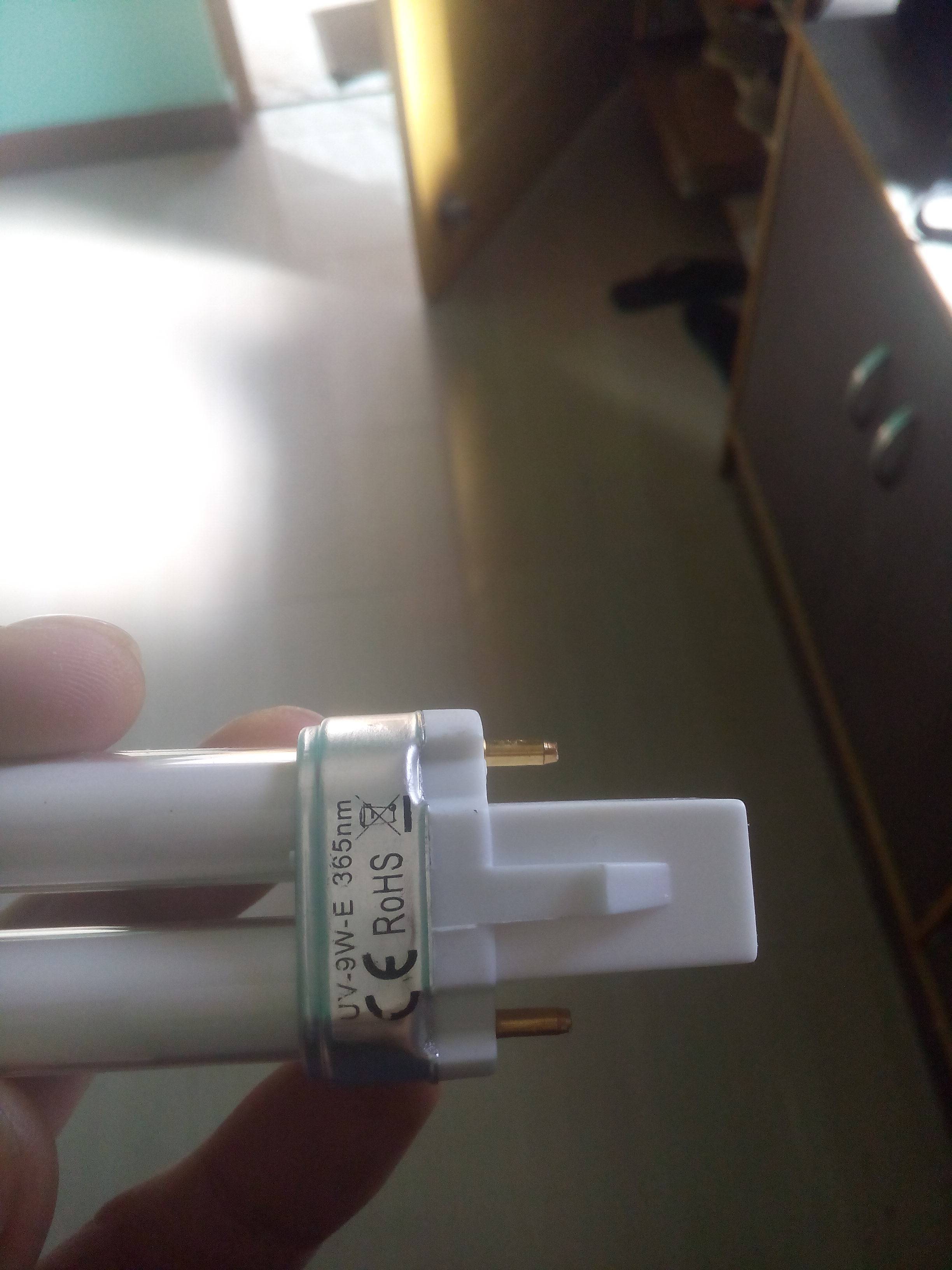
Your UV lamps are fine. They have their peak output at a wavelength of 365nm (last photo), which is well in the sensitive range of most photo resists. For example, Kontakt Chemie Positiv 20 is most sensitive for 370-440nm. That's quite astonishing, since visible light starts at 380nm. But just check what your photo resist needs.

The next problem is the plate. Normal Glass blocks UV below a given wavelength, but most acrylic blocks everything below 400nm. So you should first get a glass plate again. Fused quart glass would be superior since it doesn't block UV down to 200nm and less, but it's hard to get and expensive. May be, you don't need a plate. Put a drop of oil on your PCB and place the mask on it. The paper will soak the oil, get more transparent and stick to the PCB quite tight. But you need to remove the oil after exposure.

And finally, you need to find out the best exposure time for your new setup.

\$\endgroup\$
4
  • \$\begingroup\$ Hmm. The oil suggestions seems wonderful. Let me give that a try and report back. I was using glass as it helped keep the artwork stationary which is critical for double sided pcb. Not sure how the oil would perform as I would need to turn over the pcb to expose both sides \$\endgroup\$
    – Ankit
    Commented Nov 28, 2016 at 10:23
  • \$\begingroup\$ maybe cut the PCB after etching, not before? So you can tape/glue the mask to the extra margins. \$\endgroup\$
    – Wesley Lee
    Commented Nov 28, 2016 at 10:33
  • \$\begingroup\$ Though the drilling is often done by DIYers after etching, you could drill two holes before at positions marked on the masks, and you can align both masks to that holes. \$\endgroup\$
    – sweber
    Commented Nov 28, 2016 at 10:36
  • \$\begingroup\$ As suggested, I put a drop of oil between the artwork and the copper plate and exposed with my lamp for 5 minutes (which seemed enough as most of the videos I saw using similar setup did around 2 minute). The result was pretty much the same, the exposed area (track) was barely visible and not at all darker than the unexposed area like it should be. Also washing it in Sodium Carbonate barely turn the water blue like it does normally.This leads me to believe that it is not getting exposed properly. Couldn't be the film itself as I have tried with 2 separate stocks. Picture added in main question \$\endgroup\$
    – Ankit
    Commented Dec 1, 2016 at 6:18
0
\$\begingroup\$

I had a setup using negative photoresist and two pieces of plastic 12" x 8". I built a frame and mounted the plastic vertically, placed two CFL (curly) bulbs (one on each side) within 20 inches. The plastic was cut to fit the frame and bolts together with three bolts (two top, one bottom) and one bolt on each end to tie to the frame.

I have one PCB that I want to make which has four alignment holes. I carefully located and drilled these alignment holes through the plastic so that I can place pins through one of the plastic pieces, through the transparencies with the negative image of the front on them, through the copper clad (pre-drilled alignment holes only), through the back side transparencies and finally through the second piece of plastic. The front transparencies are aligned with the plastic pieces by pre-punching the first hole (any one of them, I usually start upper left) so that by aligning the transparency over the pre-drilled holes in the plastic, I can locate all four holes in the transparency and push a pin through the center of each of the holes using the hole in the plastic as a start guide for each pin.

The front transparencies are aligned starting with the four built-in alignment holes that I pre-punched and 2 - 4 pieces of tape applied on the edges to hold the transparency to the plastic. The pins are removed and the second transparency is aligned for best alignment on top of the first and the pin pushed through a pre-punched hole through the second transparency and left in place. A second pin is used to locate a second pre-punched hole and pushed through the second transparency and left in place. The two transparencies may then be taped together using cellophane tape while maintaining the alignment; re- adjusted until the alignment is optimum between the two. Additional transparencies may be used - I find that two are enough on each side. Also, if the transparencies are not stiff enough, the third and fourth holes may be pinned in the same manner.

Hint: I cut the sides out of the transparency and trim the edges with a paper trimmer. In my case the long side has enough space to allow me to leave one inch on both ends of the mask, so I cut one end to half inch on one of them and the other end to half inch on the other. Then the first of the two is offset from the second on both ends. When I tape them together, one end is on top and easy to access for taping. The other is easily done by laying the back (non sticky) side on the plastic and slipping it under the edge of the bottom transparency with the transparency slightly lifted and when in position press down at the top to pin the two pieces together and stick the tape to them.

Once the assembled fronts are made (taped together), the assembly may be taped to the plastic piece to hold it in place and the pins removed. Apply the same technique to locate the pin holes in the back transparency. Align it with the front transparency for maximum alignment. There might be some trouble to do this, but if it is close, it will work. (If not, you have to figure out which one is off and try to get another set of printed transparencies for it and start over.) Then while holding the transparencies in place with a couple of pieces of tape, punch through the holes as before. If everything is right, the holes should come through the mask at the alignment points on the mask.

Remove the back side mask and lay it over the plastic piece for the back (make sure that you have it positioned correctly) and verify that the pins go through the holes as punched. If all is ok, then the second back side transparency mask may be punched either on the back side plastic or on the front side plastic by attaching the first back side mask to the plastic using tape and aligning the second back side transparency mask to the first and taping it to the plastic, then punch the holes through as before. The two pieces can be taped together in perfect alignment and re-adjusted for perfect alignment by untaping/re-taping as needed.

With this setup, the pins help align the two front masks to the dual sided copper clad board and the back side masks as well as the front and rear plastic pieces. The pinned set is bolted together using wing nuts to hold the assembly together and clamp the board and masks so the pins can be removed just before exposure. The assembly is installed into the frame and held with two bolts on top and the plastic pieces against the base board.

And now to the nitty-gritty:

As I said before, the setup was tested using CFL bulbs about 20 inches away (13 watt), one on each side. Exposure was measured from 15 mins to 30 mins. The developer was applied, but there did not seem to be any evidence that UV had set anything on the board. After a couple of tries, I took the assembly outside into the sunlight for 10 minutes and the features began to appear rapidly.

So I substituted glass for the plastic (using cobbled parts and direct clamping) to see if the plastic was the problem. There was no evidence of UV coming from the CFL bulbs so, I built an array of UV LEDs 1" on center 12 LEDs per row, 7 rows. I arranged the arrays so that I can set them at 4", 6" and 7" away from the center of the assembled plastic pieces (I went back to the plastic). The first test at 4" away showed that the material turned to blue within 1 to 1.5 minutes - it was visible at 30 secs. The second test showed it to be incomplete. At least the smaller traces were very light, so I increased the time from 1.5 to 3 mins and finally to 4.5 minutes. Everything looked pretty dark.

When I developed with Sodium Carbonate, the stuff came off fairly easily, but a thin film was left behind, when I tried to take it off, the traces started to come off. I didn't time this, but I'm sure that it took a couple of minutes. Plus I stopped it and tried to restart as the film was not coming off from the unprotected areas. When the traces started to come off, I put the board into the UV for a couple of minutes and it showed material still on the board (started to darken). So I used Sodium Hydroxide to clean it off.

So my point is that I am having a similar problem although I found that upping the UV was very helpful, though I still have the same underexposed indications as yours.

I am planning to move the UV panels to 7 inches away and use a much longer exposure time, like 5 - 7 mins and also use Sodium Hydroxide for the developer. Some have said that Sodium Carbonate doesn't work well. But Sodium Hydroxide is fast so only a few seconds should do it or it will remove the traces!
\$\endgroup\$

Your Answer

By clicking “Post Your Answer”, you agree to our terms of service and acknowledge you have read our privacy policy.

Not the answer you're looking for? Browse other questions tagged or ask your own question.