0
\$\begingroup\$

Ive been teaching myself as I go so please forgive me for any errors. I need the output of an open collector output (goes to ground when active) to henerate a short negative pulse to reset the counter at 6 so it counts 0-5.

I am using a 2 74142 nixie drivers http://chronix.pl/download/74142.pdf (datasheet) For the seconds and 10 seconds digits. I use a 1Hz clock signal into the first, clear pin is set high and strobe is set low, no problems, the nixie counts from 0-9. I have the Q output cascaded to the 10 seconds digit 74142 which basically makes a 00-99 counter. I want the second counter to reset when the open collector output for digit 6 is active, thus resetting the count. I think I could do this with a second IC such as a monostable vibrator but is there a simpler way? Note that the output to digit 6 will remain active for 10 seconds. The reset pulse needs to be at least 25 ns long per the data sheet. After it resets from 5 to 0 the reset should go high again to start the counting over, meaning I want a short pulse as opposed to the reset pin being low for the whole 10 seconds.

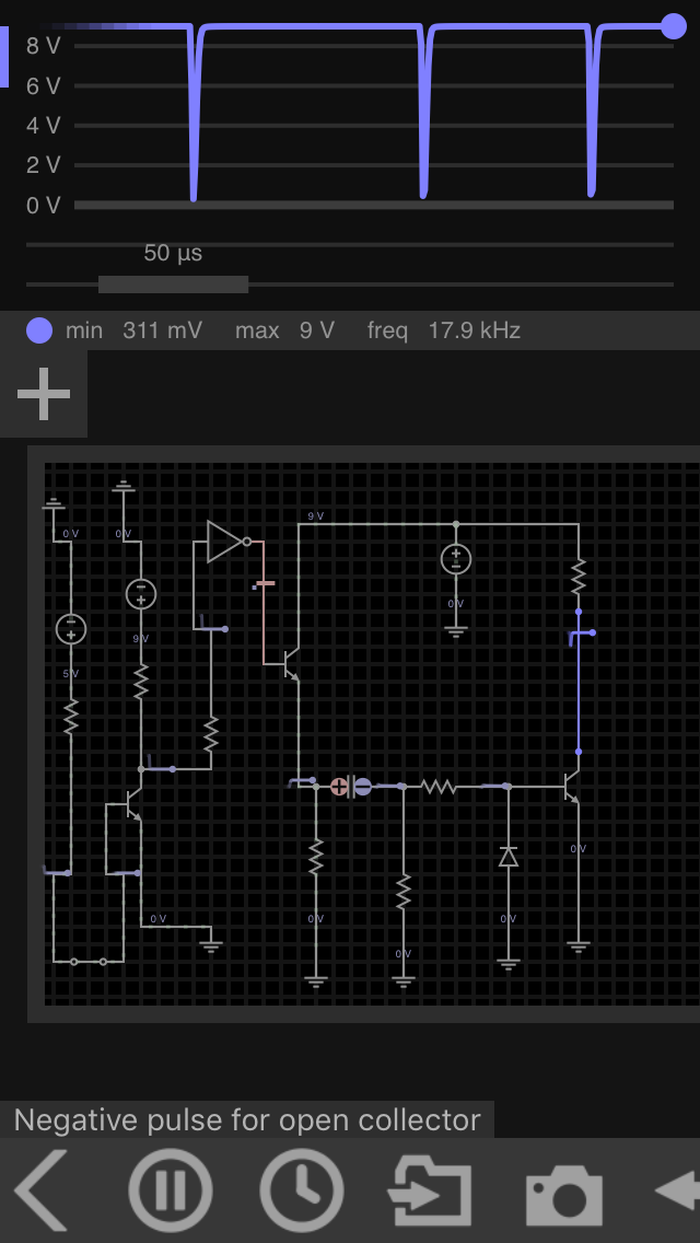
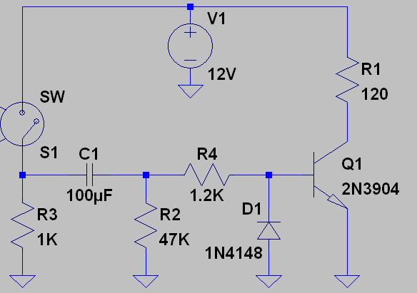
I came up with the circuit below modified from an online post. The left represents the open collector output, the spst switch activates or deactivates it. The negative pulse will be taken from the resistor on the far right. Changing C values or R values of the bottom resistors all modify the pulse width and shape. I had to add an inverter.
enter image description here

I got the original circuit from another stack exchange post. enter image description here
The only other help I found was a forum that stated the Clear pin on the 74142 should have a 2.2kOhm resistor from 5V and a 0.1 uF cap bypass to ground, and if the cap is left out it counts from 0-5. I tried this and sometimes it counts 0-5 and other times 0-6 so it is not a reliable solution. Thanks in advance for your help.

\$\endgroup\$

3 Answers 3

1
\$\begingroup\$

This is asychronous logic- when you activate the reset input the counter resets.

If you decode the count of 6 then you will get a short pulse from the propagation delay of the decoding logic. The pulse will be over once the counter resets, but you need to also ensure that the counter really resets fully.

It is recommended that the reset pulse be longer than 25ns, according to the datasheet. A typical 74xx gate has a delay of around 10ns, so if the decoding logic has at least 3 gate delays you should be okay. If there are not enough gate delays you can add a couple inverters (one fed by the other) to get another 20ns.

If you are mixing logic types (74AS types or whatever) be cognizant of the various propagation delays.

If you would prefer a nice fat pulse that is easily visible on an oscilloscope, then I would suggest using a one-shot multivibrator such as 74123.

In this case the output is a relatively high voltage sort-of open collector output that is <2.5V when sinking 7mA. So you can do something like this:

schematic

simulate this circuit – Schematic created using CircuitLab

\$\endgroup\$
3
  • 1
    \$\begingroup\$ I just set up your circuit. I had to use 74ls14 as I didnt have any 74ls04 ICs. It works! The count now goes 0-5. Thanks so much. \$\endgroup\$ Commented Dec 10, 2016 at 17:41
  • \$\begingroup\$ I only set up one digit, not 2, so does this now mean that the Q output for cascading to another 74142 cannot be used, or will it just give a divide by 6? Could I take one of the inverter outputs from the 74ls14 as the clock signal to another 74142? Or have 3 groups of 74142s each group being fed by a 1/60hz, 1/3600 Hz, 1/216000 Hz? \$\endgroup\$ Commented Dec 10, 2016 at 17:48
  • \$\begingroup\$ If the digit is divide by 6 you can use the LS14 output as the clock for the next digit. \$\endgroup\$ Commented Dec 10, 2016 at 17:53
0
\$\begingroup\$

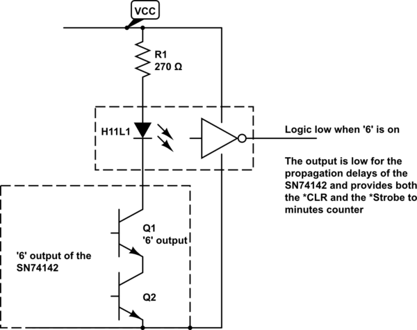
Unfortunately, you can't detect your '6' any other way than by looking at the high voltage driver state of the SN74142.

You don't need to create a short reset pulse at all (it's asynchronous) since when the '6' is on the counter is in an illegal state (from your perspective), but in addition the QD output no longer works to increment your minutes digit, so you need to generate this too using the same signal.

While in the time of this type of logic you might use yet more logic to detect the digit states, I think you can do this with more modern devices and much less logic and pulse creation difficulties.

You need to detect the '6' digit on and can then simply pull low the *CLR. Eventually the '6' digit will turn off after the signal propagates through the counter and the output driver. This time is not specified, but is likely to be at least in the 50-60 nS range.

I'd try something like this (though I have not tried it out, so it's just a suggestion):

schematic

simulate this circuit – Schematic created using CircuitLab

The H11L1 has a logic level inverter as it's output instead of the more usual open collector that you see. The 270 Ohm resistor should provide at least 5 mA through the input LED and you can see from Figure 3 that the device has a nice threshold at 1 mA.

This might work for both the tens(seconds) and tens(hours), and would even allow you to put in jumpers (short out the input LEDS) to make a general purpose clock or timer display. May be useful (or not).

\$\endgroup\$
1
  • \$\begingroup\$ Thanks, I'll give your circuit a try. Most people use 7441 which has a BCD input/nixie decoder and use the BCD inputs to create a logic circuit to reset on 6. I have the ICs to do that but wanted to try using the 74142 first. They were made to drive nixies so I'm surprised there isn't a trivial way to reset the counter at 6 but maybe I assume the ICs were not made for time display but for frequency counting where a reset on 6 isnt needed. I could always fall back on using a uC but as I am learning as I go, I'd rather stick with discrete components. \$\endgroup\$ Commented Dec 9, 2016 at 20:48
0
\$\begingroup\$

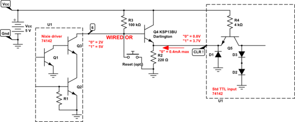
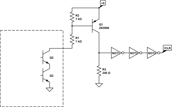
With 6 active low and Clear input active low, the Clear just needs to be OR'd with your reset switch and output (6) using a pullup R3 and reset switch, if you have one.

The 74142 driver is a High Voltage (60V) Open Collector driver , and does not meet std TTL input level for logic "0' so a level shifter is needed such as a Darlington small signal $0.22 TO-92. R2 for emitter satisfies the logic "0" for the standard TTL input for CLR.

The dotted line shows what is actually inside the 74142 TTL counter/decoder/driver.

schematic

simulate this circuit – Schematic created using CircuitLab

The pulse width on output (6) is guaranteed to only be as long as it takes for CLR to reset the counter and may easily be stretched with 100pF ~0.1uF on Output (6) to ground. This should be 25ns min.

\$\endgroup\$
1
  • \$\begingroup\$ Stewart. Unfortunately the 6 active low has a very high output voltage (around 2 V or more) so will likely not pull a logic low on a TTL input. \$\endgroup\$ Commented Dec 9, 2016 at 19:55

Your Answer

By clicking “Post Your Answer”, you agree to our terms of service and acknowledge you have read our privacy policy.

Not the answer you're looking for? Browse other questions tagged or ask your own question.