0
\$\begingroup\$

I've built a motorhome-type vehicle, and wish to perform coulomb counting for the battery bank. I've placed a 100A/75mV shunt between the battery bank negative, and the negative bus (which is also connected to vehicle chassis to reduce wiring cost for alternator charging etc.)
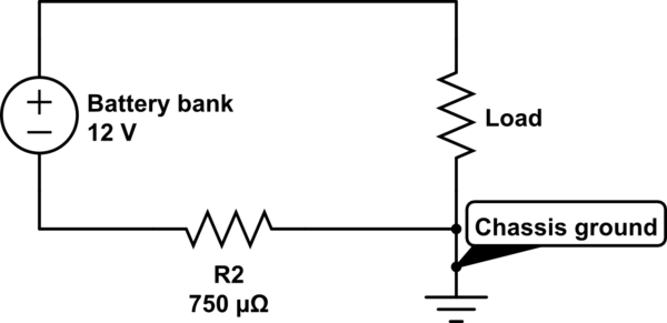
schematic

simulate this circuit – Schematic created using CircuitLab

How can I most accurately measure the mV across the shunt? The value will typically be 1-10 mV, up to 100 mV peak, and will be either positive or negative, depending on the direction of the current.

I understand that I may need an inverting amplifier, since the microcontroller will be grounded at the load level, e.g. unable to measure a negative voltage. Or is it sufficient just to use offsetting?

I'm new to amplifiers, and worried that I'll spend countless hours trying to get the wrong components to work, particularly having difficulties accurately reading the 1-5mV level.

Typical usage, as measured across the shunt with a multimeter: - Charging at 20-30A = (negative) 15-22mV - Constant loads, ventilation etc., 1-2A = 0.75-1.5mV - Peak charging from alternator 50-80A = (negative) 38-60mV

The multimeter reads the values quite well/stable.

\$\endgroup\$
6
  • \$\begingroup\$ I think the bigger problem is likely going to be dealing with the uncompensated accumulation (or de-accumulation.) You may need to figure out some method of automatically compensating the offsets to minimize that error (and/or using precision devices that have been calibrated against accuracy standards.) But how important this actually will be depends on details you haven't discussed about your usage, needs, and operational behavior overall. \$\endgroup\$
    – jonk
    Commented Dec 15, 2016 at 21:37
  • \$\begingroup\$ I'm not sure what you mean. I've searched google for "uncompensated accumulation electronics", but I didn't find any articles discussing the problem. Would you have a source where I could read more about it, e.g. what to expect and how to reduce problems? \$\endgroup\$ Commented Dec 15, 2016 at 21:46
  • 1
    \$\begingroup\$ Google up "battery monitor IC" -- you will find a number of them and they often discuss the problem and some solutions, it seems. TI's bq26220 came up right away -- and it mentions it. But I'm not looking into the datasheet. You can do that, and/or check out others as well. So I'm not entirely wrong about the concern, it seems, now that I looked. (Which is nice to know, as I'm only going on math knowledge about integrating, generally.) \$\endgroup\$
    – jonk
    Commented Dec 15, 2016 at 22:28
  • \$\begingroup\$ I think he's talking about the way errors can add up when coulomb counting. If you're trying to keep track of the charge state over time, and you always have a small (random) error in your measurements, then as you add those measurements together, the error accumulates. Eventually, instead when the charge goes from 10% to 30% the electronics will tell you it's gone from 140% to 160%, or -5% to 15% or whatever. You'll need to occasionally reset it to zero or full. \$\endgroup\$
    – Jack B
    Commented Dec 15, 2016 at 22:28
  • 1
    \$\begingroup\$ I wasn't recommending that chip for your situation. You asked what I meant and I was merely pointing it out as the first google entry that came up in the search I suggested you try out. \$\endgroup\$
    – jonk
    Commented Dec 16, 2016 at 6:24

3 Answers 3

1
\$\begingroup\$

I'd suggest this as prerequisite reading for you. There are several article parts (see end of page two) that cover most of the fundamentals.

TI make excellent High and Low side Current monitors INA138 (you need two of these to do bi-directional, see Figure 15 in datasheet), the automotive INA169 (again you need two) and INA210.

Configuring amps for low side detection can be more challenging, so I'd recommend using High side measurements (it makes no difference to your system).

If you are committed to using Low side detection them you can use the LM3900 Norton opamps to obviate having to use negative supplies. Again here, you'd have to have separate LM3900's for charge discharge sensing (though only a single sense shunt resistor).

I'd recommend use of the INA169, it's really easy to use and there is a small PCB version available from Sparkfun for $9.

\$\endgroup\$
4
  • \$\begingroup\$ Super input, thanks! Perhaps I can swap the battery clamps can get a high side shunt instead (all the wiring is heavy gauge, cut to length etc. so moving the shunt would be quite a pain). And it'd be easier not to deal with negative voltage on the input. Do you know the difference between these 'current monitors' as opposed to just using ordinary opamps/instrument amplifiers? \$\endgroup\$ Commented Dec 15, 2016 at 23:17
  • \$\begingroup\$ The reason I need two, is that when the V- is greater than V+, Vout will be zero? (e.g. when the 12V bus bar is at a higher voltage than the battery terminal, because a higher voltage is supplied from the alternator) \$\endgroup\$ Commented Dec 15, 2016 at 23:19
  • \$\begingroup\$ @user95482301. Correct, and the INA169 is configured for only reading when Vin+ is more positive than Vin-. The grounds are of course common so the buffered voltage value is relative to ground in both cases. As others have indicated, measuring Ah status is challenging. The bq26220 mentioned above is definitely out of scope for you as it is meant to be driven by the host microprocessor to store accumulation values in the flash ....it's way too complex for you I would imagine. +this: electronics.stackexchange.com/questions/212723/… \$\endgroup\$ Commented Dec 16, 2016 at 0:21
  • \$\begingroup\$ thanks for the link. I have to say though, that guy is crazy. Drawing 200A from lead acid batteries to power a space heater? :D \$\endgroup\$ Commented Dec 16, 2016 at 0:34
1
\$\begingroup\$

You can get op-amps that are dc accurate down to a handful of micro volts so there's no problem there but, given that the current can be negative as well as positive I'd create a small negative supply to power the op-amp symmetrically about the ground point. Then I'd go for something like an OPA333 as the op-amp. If you need more bandwidth then something like an ADA4528 is also good.

If you are looking for budget parts - you get what you pay for.

Basically run the op-amp as a non-inverting amplifier and add offset to centralize the signal produced into the range of your microprocessor's ADC.

You might even consider a low offset-voltage Instrumentation Amplifier like the AD8222 fed from a symmetrical supply - it has a pin you can set for the offset called "REF".

You can get very cheap DC-to DC converters (very small too) that can be wired to take a positive supply voltage and produce a stable negative output voltage.

\$\endgroup\$
1
\$\begingroup\$

There's a product category called "current sense amplifiers" designed for just this scenario, where voltage across a shunt resistor must be read outside the supply rails of the amplifier.

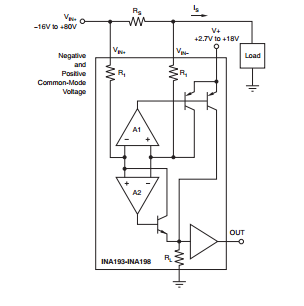
Most of these parts are designed only to work with input voltages at or above the positive rail, but a few allow measurement below the negative rail. For example, INA193 can measure differential voltages offset from -16 to +80 V:

enter image description here

You can also look at the datasheets of these parts to see the circuit topology that allows measuring outside the rails, and reproduce it with discretes, although accuracy might suffer from not having components as well matched as you might get on-chip.

\$\endgroup\$

Your Answer

By clicking “Post Your Answer”, you agree to our terms of service and acknowledge you have read our privacy policy.

Not the answer you're looking for? Browse other questions tagged or ask your own question.