1
\$\begingroup\$

I've been given a word problem, and I must make a state diagram followed by a state table.

The problem reads Design a circuit that has two inputs, clk and X and produces output O. X may change every clock cycle and the change happens at the falling edge. The circuit samples the input at every rising clock. O = 1 if the last values of X over the last three cycles were 101.

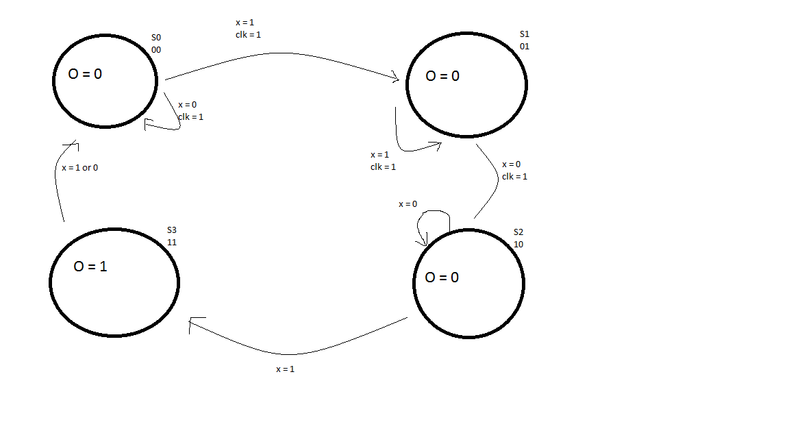
Here is the diagram I made This is the diagram I made

I lost points on it, and my professor said it is supposed to look like this enter image description here
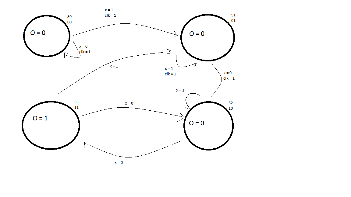
I don't quite understand this. I get that from S3, if X = 1, it goes back to S1, because when X is 1, we have made progress towards 101. However, why does S2 go to S3 when X is 0 and not 1? And why does S3 cycle back to S2 at 0?

\$\endgroup\$

1 Answer 1

1
\$\begingroup\$

The key idea is that input 10101 needs to output 1 twice, since 101 appears twice in the input sequence. Your state machine won't notice the second 101 sequence.

In the solution, S1 indicates you have a 1, S2 indicates you have 10, S3 indicates you have 101, and S0 indicates you have 0 without a 1 before it. (To answer your question, S3 goes back to S2 when you get a 0, because you now have 10 and are waiting for a 1.)

The solution diagram looks like the arrows from S2 to S3 are wrong; you should move from S2 to S3 when you get a 1 and S2 to S0 when you get a 0.

\$\endgroup\$
1
  • \$\begingroup\$ Thank you, this clarifies it. The thing that really threw me off was going to S3 with a 0 but that must have been a typo in his email \$\endgroup\$ Commented Dec 16, 2016 at 2:18

Your Answer

By clicking “Post Your Answer”, you agree to our terms of service and acknowledge you have read our privacy policy.

Not the answer you're looking for? Browse other questions tagged or ask your own question.